Exercise 9: ADC and DAC
Introduction
The ESP32 comes with two 12 bit ADCs and two 8 bit DACs. In this exercise we will see how to use them and what their limitations are.
Exercise 1: Basic ADC use
Read the ADC and DAC descriptions on this TWiki:
ADC and DAC. Connect the analogue joystick to the ADC channels on pin 32 and 34 on the CPU card (not on the WeMos D1 mini bus!). Set the ADC attenuation to 11 dB. Read both joystick channels (hor and ver) once per second and print the results.
Exercise 2: Linearity check
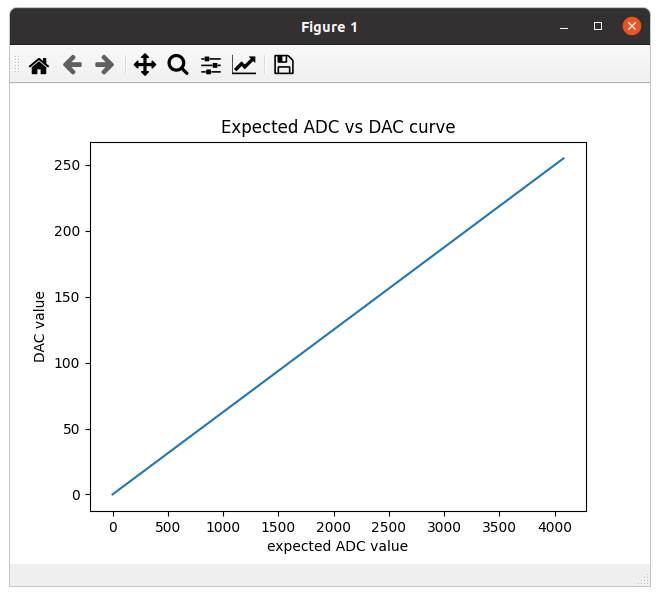
Connect the DAC (pin D0 or GPIO 26 ) to the ADC (pin A0 or GPIO 36). Set the ADC attenuation to 11 dB. Write a program which ramps up the DAC from 0 to its max value 255 and which reads the ADC at each step. Write the ADC values to a file, transfer it to your laptop and plot the result.
This is what you would expect to get:
Exercise 3: Check with external ADC
You will see in exercise 2 that the DAC/ADC system is not linear. Try to find out if it is the DAC or the ADC which introduces the non-linear behavior replacing the ESP32 ADC by an external ADS1115 16 bit ADC. You can find the driver software for the ADS1115 at
https://github.com/robert-hh/ads1x15.
Exercise 4: Compensating the non-linearity by software
As you will see in exercise 3 that the non-linearity comes from the ADC and that the DAC is perfectly linear, you can compensate the non-linearity by software. On the TWiki page
ADC and DAC it is explained how this is done. Follow the explication and create a polynomial fit to the inverse of the ADC vs DAC curve. Use this polynomial to do the correction. Try another ADC vs DAC measurement applying the correction and make sure that you correction works.
Exercise 5: A simple pulse generator
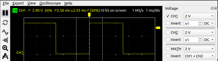
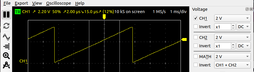
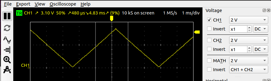
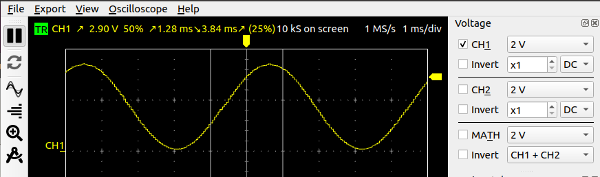
The DAC can be used to create a simple pulse generator for different wave forms. Create a Python program that pre-calculates a
- sine
- rectangular
- sawtooth
- triangual
wave form and sends these data to the DAC. The wave forms are pre-calculated such that the values stored in a list can be sent to the DAC quickly and at regular intervals (different time intervals due to different calculation times are eliminated). Observe the wave forms on an oscilloscope. This is what you would get:
The exercise sheet in odt format:
https://iotworkshop.africa/pub/IoT_Course_English/ADCAndDACExercises/exercise_9.odt
-- %USERSIG{UliRaich - 2020-07-31}%


 odt
 png