
Lecture 3: Switches
CSC 321: Embedded Sysytem
First Semester 2020/2021
Types of Switches
Toggle Switches
 Toggle switches are actuated by a lever angled in one of two or more positions.
The common light switch used in household wiring is an example of a toggle switch.
Pushbutton Switches
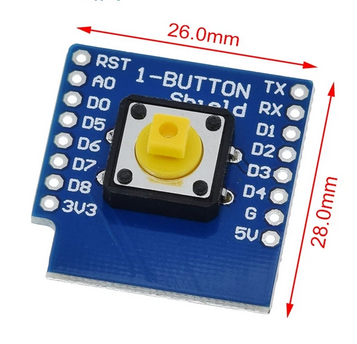
 Pushbutton switches are two-position devices actuated with a button that is pressed and released.
Most pushbutton switches have an internal spring mechanism returning the button to its \x93out,\x94
or \x93unpressed,\x94 position, for momentary operation.
Types of Switches
Selector Switches
 Selector switches are actuated with a rotary knob or lever of some sort to select one of two or more positions.
Joystick Switches
 A joystick switch is actuated by a lever free to move in more than one axis of motion.
One or more of several switch contact mechanisms are actuated depending on
which way the lever is pushed, and sometimes by how far it is pushed.
Pressure Switches
 Gas or liquid pressure can be used to actuate a switch mechanism if that pressure is applied to a piston,
diaphragm, or bellows, which converts pressure to mechanical force.
Temperature Switches
 An inexpensive temperature-sensing mechanism is the \x93bimetallic strip:\x94 a thin strip of two metals,
joined back-to-back, each metal having a different rate of thermal expansion.
The Push Button & PIR
 |
 |
Digital Inputs
When you try to use a microcontroller to detect activity in the physical world, the simplest activity you can perceive is whether an activity is True or False.- Is the audience in the room or outside?
- Are they touching the table?
- Is the door open or closed?
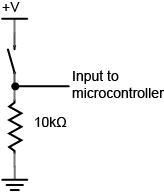 From the schematic diagram current has two directions it can go to ground:
through the resistor or through the microcontroller. When the switch is closed, the current will follow the path of least resistance, to the microcontroller pin,
and the microcontroller can then read the voltage. The microcontroller pin will then read as high voltage or HIGH. When the switch is open, the resistor connects the digital input to ground, so that it reads as zero voltage, or LOW. \x95 A digital input is a board pin which can read if it sees a high (on) or low (off) logic level connected to it. \x95 For example if you connect a button to a digital input you can detect when it's pressed and released. \x95 Also if you connect a PIR(passive infrared sensor) to a digital input, it can detect the infrared (IR) light radiating from objects in its field of view. \x95 MicroPython makes it just as easy to use a pin digital inputs as it does outputs.
Pull-up Resistors
\x95 Pull-up resistors are very common when using microcontrollers (MCUs) or any digital logic device.` \x95 The value of the pull-up resistor needs to be chosen to satisfy two conditions: \x95 When the button is pressed, the input pin is pulled low. The value of resistor R1 controls how much current you want to flow from VCC, through the button, and then to ground. \x95 When the button is not pressed, the input pin is pulled high. The value of the pull-up resistor controls the voltage on the input pin.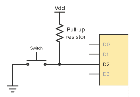
The PIR Sensor
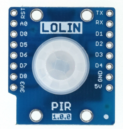
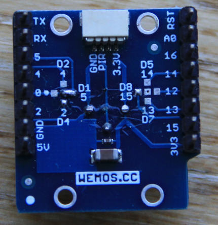
\x95 PIR sensors allow you to sense motion, almost always used to detect whether a human has moved in or out of the sensors range. \x95 They are small, inexpensive, low-power, easy to use and don't wear out. \x95 They are often referred to as PIR, "Passive Infrared", "Pyroelectric", or "IR motion" sensors. \x95 PIR is an electronic sensor which detects the changes in the infrared light across certain distance and gives out an electrical signal at its output in response to a detected IR signal. \x95 It can detect any infrared emitting object(Objects that generate heat) such as human beings or animals if it is the range of the sensor, or moves away from the range, or moves within the range of the sensor. \x95 The radiation of the infrared object should be strongest at a wavelength of 9.4μm. \x95 Infrared in this range will not pass through many types of material that pass visible light such as ordinary window glass and plastic. \x95 However it will pass through, with some attenuation, material that is opaque to visible light such as germanium and silicon.| |
 |
PIR Sensitive Crystal
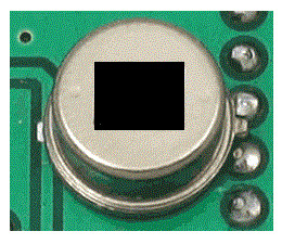 There are two important materials present in the sensor:
- The pyroelectric crystal which can detect the heat signatures from a living organism (humans/animals)
- The Fresnel lenses which can widen the range of the sensor.