Difference: ASteppingMotor (1 vs. 2)
Revision 22017-10-09 - uli
| Line: 1 to 1 | ||||||||
|---|---|---|---|---|---|---|---|---|
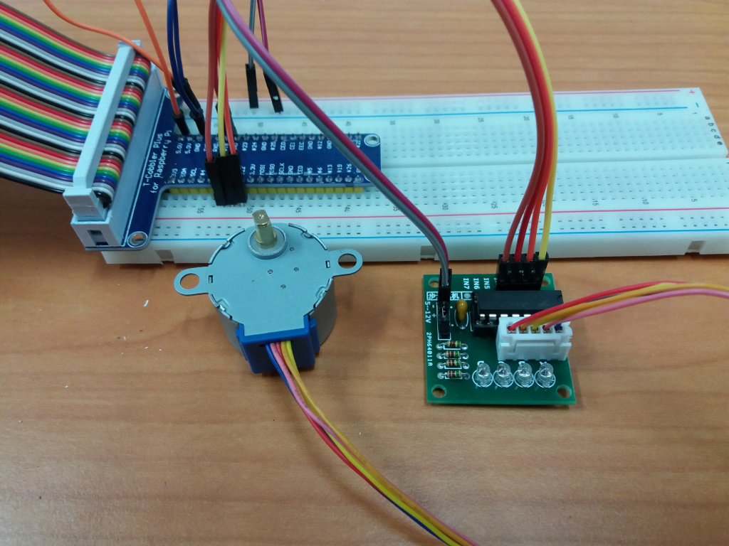
Stepping MotorThe Raspberry Pi's GPIO pins can also be used to generate the signals needed for the different phases of a stepping motors. Driving a stepping motor in his different modes of operation is one of the exercises that the students will prepare during the lab session. A simplified version of the program will be demonstrated during the Open Day making the motor clock-wise or counter-clock-wise. | ||||||||
| Changed: | ||||||||
| < < | The photo shows the stepping motor itself as well as its driving circuit (the little PCB). This driving circuit can be controlled through the embedded system (the connection is made through the four pins you see behind the driver chip) and by doing so the motor will move into the wanted direction and for the number of steps selected. | |||||||
| > > | The photo shows the stepping motor itself as well as its driving circuit (the little PCB) as it is connected to the Raspberry Pi cobbler (blue PCB on the left of the photo with flat cable connection to the Raspberry Pi processor board). This driving circuit can be controlled through the embedded system (the connection is made through the four pins you see behind the driver chip) and by doing so the motor will move into the wanted direction and for the number of steps selected. | |||||||
| Changed: | ||||||||
| < < |  | |||||||
| > > |  | |||||||
|
-- | ||||||||
| Line: 14 to 14 | ||||||||
| Changed: | ||||||||
| < < |
| |||||||
| > > |
| |||||||
Revision 12017-10-06 - uli
| Line: 1 to 1 | ||||||||
|---|---|---|---|---|---|---|---|---|
| Added: | ||||||||
| > > |
Stepping MotorThe Raspberry Pi's GPIO pins can also be used to generate the signals needed for the different phases of a stepping motors. Driving a stepping motor in his different modes of operation is one of the exercises that the students will prepare during the lab session. A simplified version of the program will be demonstrated during the Open Day making the motor clock-wise or counter-clock-wise. The photo shows the stepping motor itself as well as its driving circuit (the little PCB). This driving circuit can be controlled through the embedded system (the connection is made through the four pins you see behind the driver chip) and by doing so the motor will move into the wanted direction and for the number of steps selected. --
-- Comments
| |||||||
View topic | History: r2 < r1 | More topic actions...
Ideas, requests, problems regarding TWiki? Send feedback