Difference: TinyMLOnTheEsp32s3-wroom (2 vs. 3)
Revision 32023-09-02 - UliRaich
| Line: 1 to 1 | ||||||||||
|---|---|---|---|---|---|---|---|---|---|---|
| ||||||||||
| Changed: | ||||||||||
| < < | TinyML on the esp32-cam | |||||||||
| > > | TinyML on the esp32s3-wroom | |||||||||
Introduction | ||||||||||
| Changed: | ||||||||||
| < < | The esp32-cam is a very cheap esp32 board with 4MB PSRAM and an integrated OV2640 | |||||||||
| > > | The esp32s3-wroom is a very cheap esp32s3 board with 8MB of octal PSRAM and an integrated OV2640 | |||||||||
| Changed: | ||||||||||
| < < | The disadvantage of this module is the limited number of GPIO pins that can be accessed for general use. https://randomnerdtutorials.com/esp32-cam-ai-thinker-pinout | |||||||||
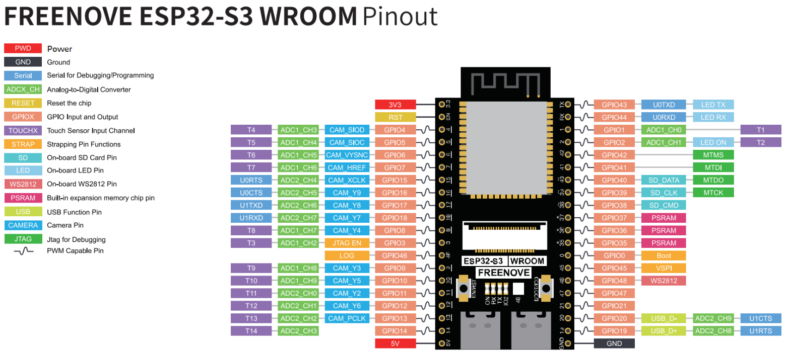
| > > | The module has 40 external piins of which many are used internally however. | |||||||||
| Changed: | ||||||||||
| < < | The module has 16 external pins, of which already 6 are used for power and ground. There are 2 pins, of which either one can be used to power the esp32-cam marked, 5V and 3V3. The pin labelled Vcc should not be used to power the board, it is in fact an output pin. | |||||||||
| > > |  | |||||||||
| GPIO 1 and 3 are the serial Tx and Rx respectively. If you have a board with a USB connector, then these pins stay unused. In the other case, you must connect the board to your PC through these pins for serial communication and for flashing, using an USB to serial converter. When connecting GPIO-0 to ground and resetting the esp32-cam it enters into flash mode. For normal operation, this connection must be removed. | ||||||||||
| Changed: | ||||||||||
| < < | The esp32-cam features a SD-card interface using GPIO 14,15,2,4,12,13. GPIO 4 is also used for the flashlight. These pins are available as regular inputs/outputs if the SD card is not used. For more details, you may consult the circuit diagram: https://iotworkshop.africa/pub/IoT_Course_English/TinyMLOnTheEsp32s3-wroom/ESP32_CAM_V1.6.pdf | |||||||||
| > > | The esp32s3-wroom features a SD-card interface using GPIO 14,15,2,4,12,13. GPIO 4 is also used for the flashlight. These pins are available as regular inputs/outputs if the SD card is not used. | |||||||||
Connecting the MPU6050 accelerometer and gyroscopeThe MPU6050 accelerometer and gyroscope is used in the magic wand example. | ||||||||||
| Line: 38 to 35 | ||||||||||
| ||||||||||
| Deleted: | ||||||||||
| < < | ||||||||||
-- Comments | ||||||||||
| Changed: | ||||||||||
| < < | ||||||||||
| > > | ||||||||||
| ||||||||||
| Added: | ||||||||||
| > > |
| |||||||||
View topic | History: r3 < r2 < r1 | More topic actions...
Ideas, requests, problems regarding TWiki? Send feedback