Difference: VirtualInstruments (1 vs. 3)
Revision 32021-05-16 - UliRaich
| Line: 1 to 1 | |||||||||||
|---|---|---|---|---|---|---|---|---|---|---|---|
Virtual InstrumentsIntroduction | |||||||||||
| Changed: | |||||||||||
| < < | Measurement instruments like multi-meters, pulse generators or oscilloscopes can be rather costly and the requirements for the IoT course are rather modest with respect to signal height (we have either digital signals of 0 or 3.3V or analogue signals in the same range) or with respect to frequency (a few kHz max). | ||||||||||
| > > | Measurement instruments like multi-meters, pulse generators or oscilloscopes can be rather costly and the requirements for the IoT course are rather modest with respect to signal height (we have either digital signals of 0 or 3.3V or analogue signals in the same range) or with respect to frequency (a few kHz max). | ||||||||||
| The ESP32 has a Digital to Analogue Converter (DAC), which can be uses to generate signals of any shape, and it has an ADC which can be used to sample analogue signals. | |||||||||||
| Line: 34 to 34 | |||||||||||
| |||||||||||
| Changed: | |||||||||||
| < < | It works on the same principles as the voltmeter: The pulseGenServer.py is a TCP server which allows connection from a GUI application pulseGenGUI.py serving as TCP client. This application controls the settings of the pulse generator sending commands to the pulseGenServer: | ||||||||||
| > > | It works on the same principles as the voltmeter: The pulseGenServer.py is a TCP server which allows connection from a GUI application pulseGenGUI.py serving as TCP client. This application controls the settings of the pulse generator sending commands to the pulseGenServer: | ||||||||||
| |||||||||||
| Added: | |||||||||||
| > > |
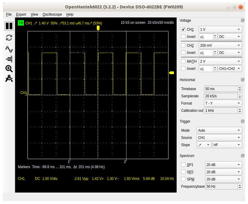 The image shows the oscilloscope trace for a square pulse at 5 kHz. A pulse length of 100 ms is expected, and we can see that the time between the markers, corresponding to 2 pulses, reads 201 ms.
 | ||||||||||
|
-- | |||||||||||
| Line: 49 to 60 | |||||||||||
| |||||||||||
| Added: | |||||||||||
| > > |
| ||||||||||
Revision 22021-05-16 - UliRaich
| Line: 1 to 1 | ||||||||
|---|---|---|---|---|---|---|---|---|
Virtual InstrumentsIntroduction | ||||||||
| Line: 18 to 18 | ||||||||
An application with a Graphical User Interface (GUI), created with the Qt5 library implements a TCP client that connects to the server, gets the measured data from it and displays them in a user-friendly manner. Measurement parameters, like the pulse shape and frequency in case of the pulse generator can also be set using GUI elements.
A Virtual Voltmeter | ||||||||
| Changed: | ||||||||
| < < | The simplest of the virtual instruments is certainly the Voltmeter.
| |||||||
| > > | The simplest of the virtual instruments is certainly the Voltmeter. The analogue signal level must be connected to GPIO 36 (first ADC channel). Then the voltmeterServer.py must be started on the ESP32:
 As you can see, the server has IP: 192.168.1.98 (this will very probably be different on your machine) and it waits for connections requests on port 5000.
Once the server is running you can start the GUI application on the PC and connect to the server (in the example above the PC has IP 192.168.1.36). Once the connection is established the signal level is shown in analogue form (the gauge) as well as in digital form. The values are in volts.
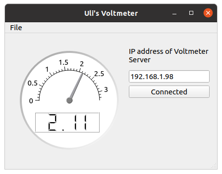
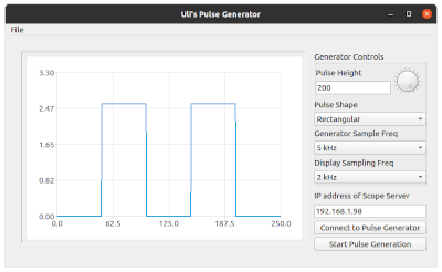
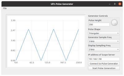
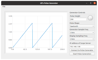
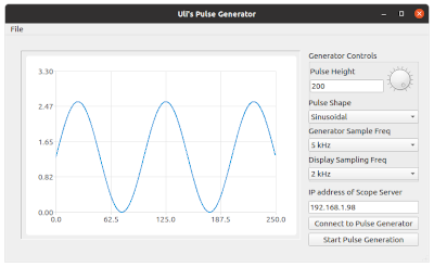
The pulse generatorThe pulse generator provides 4 different pulse shapes:
| |||||||
-- Comments | ||||||||
| Added: | ||||||||
| > > |
| |||||||
Revision 12021-05-15 - UliRaich
| Line: 1 to 1 | ||||||||
|---|---|---|---|---|---|---|---|---|
| Added: | ||||||||
| > > |
Virtual InstrumentsIntroductionMeasurement instruments like multi-meters, pulse generators or oscilloscopes can be rather costly and the requirements for the IoT course are rather modest with respect to signal height (we have either digital signals of 0 or 3.3V or analogue signals in the same range) or with respect to frequency (a few kHz max). The ESP32 has a Digital to Analogue Converter (DAC), which can be uses to generate signals of any shape, and it has an ADC which can be used to sample analogue signals. Three types of instruments have been implemented:
A Virtual VoltmeterThe simplest of the virtual instruments is certainly the Voltmeter.--Comments | |||||||
View topic | History: r3 < r2 < r1 | More topic actions...
Ideas, requests, problems regarding TWiki? Send feedback
