Exercises
First exercise session:
A bit of programming
Connect your ESP32 to the PC using the micro USB cable and start thonny. Locate the shell window and check if you see the REPL prompt ">>>". If not, try to press <enter>. Make sure the shell window has the input focus. If this does not work, press the stop button. If this also doesn't help, press the reset button on the ESP32 CPU board.Playing with REPL
- print "Hello World!"
- calculate 127,9 * 157.6 * 17.2 /(3.5*2**4), 2**4 means 2 to the power of 4
you may try to calculate e.g 2**4 separately first and check that you get the result expected - continue experimenting with REPL
Hello World
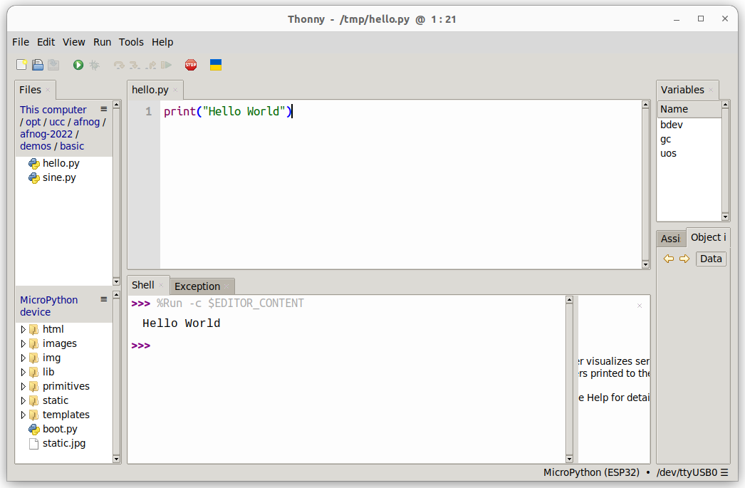
Instead of working on the shell window, we will now write a Python script (a small program). For this to work, select File -> New. This will create an editor window named <untitled>. Save this empty program to the disk on your PC. Select File -> Save, select "This Computer" give it a file name (e.g. hello.py) and press "OK". The window title changes to hello.py. Now enterprint("Hello World!")
Finally, run the program by pressing the green button with the white triangle. You should see "Hello World!" printed in the shell window. This is what you should get:
Some Arithmetic
Assign 2 values to 2 variables a and b. Calculate the sum, the difference, the product and the division and print the results. Start assigning integer values. Try integer and float division. Then assign float values and try again.Conditions
Assign again 2 values to 2 variables a and b with a being bigger than b . In your program, check if a is equal, bigger or smaller than b. Modify the values you assign to a and b, with b now bigger than a and try again. In the lectures, we used the "<" and the ">" conditions to find out, if the value in the variable a is bigger, smaller or equal to the value in variable b. Can you modify the program using "<" and "!=" to find out? What happens if you test:if a:
print("yes")
else:
print("No")
Try this with a being assigned to zero and a being assigned to 7. What do you conclude?
Loops
Write a script that prints "Hello World!" forever. You can stop the program with the red Stop button. Write a program that prints "Hello World!" 7 times. Do this using a while loop and in a second program, using a for loop, Which of the programs is more elegant?Too easy? Calculate the Fibonacci numbers
The Fibonacci numbers are defined as follows:- F(0) = 0
- F(1) = 1
- F(n) = F(n-1) + F(n-2)
This is the end of the first exercise session
Second exercise session
MicroPython modules
Modify the loop program in such a way that "Hello World!" is printed only every second. Import the time module and make the program sleep for 1s after each print statement. Import the sin function and the value of pi from the math modulefrom math import sin,piRemember that the sin function takes its values in units of radians. The angle values for a complete sin period will range 0 .. 2*pi. Print the angles and the sin values for a full sin period using 30 equidistant angle values. (x and sin(x)).
Creating and using your own function
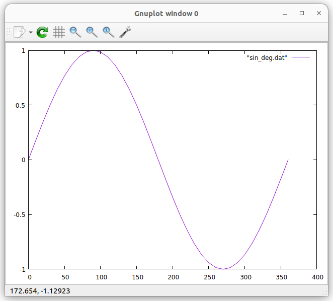
Create a sin_deg function which takes angles in units of degrees instead of radians. Print the angles and the sin values for 36 equidistant angle values. You may copy/paste the result to a new editor window in thonny and save them to a file on the PC. Then you can plot the function using gnuplot.- run guplot
- in gnuplot enter:
plot "your_data_file.dat" with lines
Too easy? Calculate the throwing parabola
If the above is too simple for you, you may try to calculate the throwing parabola. Let's say, a stone is thrown at a speed of 30m/s and an angle of 30° with respect to ground. Calculate the trajectory of the stone until it hits the ground. You may define a function trajectory, taking as parameters the initial speed, the angle and the time resolution for which you want to calculate the stone positions.v_hor = v_initial * cos(angle) v_ver = v_initial * sin(angle) x(t) = v_hor * t y(t) = v_ver * t - 1/2 * g * t**2Like this, you can easily calculate the trajectories for different angles and different initial speeds.
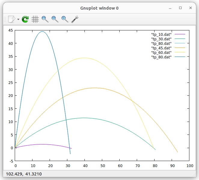 tp_10 is the trajectory for 10 degrees.
tp_45 is the trajectory for 45 degrees.
Plotting is done as described above. When plotting several data files, use
replot "data_file.dat" with linesin order to avoid deleting the previous plot.
Improving the program
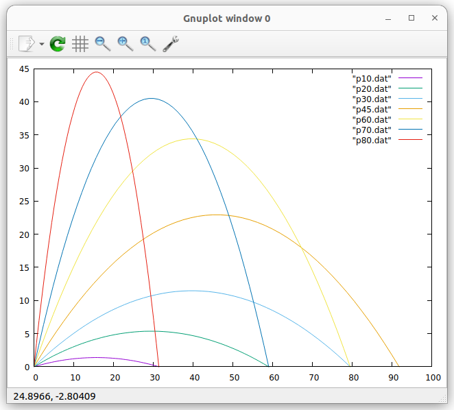
This program can further be improved by plotting the same number of points for each parabola. To achieve this, we can first calculate the total flight duration until the object hits the ground again:vt = 1/2*g*t**2, v => 1/2*g*t, t= 2*v/gThen we calculate a fixed number of points (e.g. 50) for each parabola in a for loop. Like this, we can easily see that for an angle of 30° and 60° the distance covered is the same. This is also true for 10° and 80° or 20° and 70°.
End of the second exercise session
Third exercise session
Programming the user LED on the CPU card
Write a program that blinks the user programmable LED on the CPU card at a frequency of 1 Hz (500 ms on, 500 ms off) Write a function that blinks the LED once with a delay that is passed as a parameter:def blink_once(delay):Test the function with a main program calling it with different delays. Use the function to implement a program that blinks an SOS: 3 short pulses, followed by 3 long pulses, followed by 3 short pulses, followed by a 2s pause. You may use a 200 ms delay for the short pulses and 700 ms delay for the long ones.
Reading the pushbutton
Write a program that reads the push button state every 100 ms and prints its state (pressed or released) Improve the program printing the state only when there was a state change.Too easy? Change the light intensity on the LED using PWM
Write a program that linearly increases the light intensity of the user programmable LED using Pulse Width Modulation ( PWMFourth exercise session
Reading an analogue signal level from the slider potentiometer
- Read the documentation of the ADC driver
 in the MicroPython manual
- Connect the potentiometer to the triple base according to the table in Analogue Signals#PotConnections
- Create an ADC object and make sure you set the attenuator to 11 dB
- Read the slider value every 100 ms and print its raw 12 bit value
- Move the slider and observe the changes in the value
Controlling the rgb LED ring
The LED ring consists of 7 WS2812B addressable and cascadable LEDs. Each rgb LED consists of 3 tiny single color LEDs emitting red, green and blue light. The color you finally see is the mixture between these color components. The MicroPython driver for this type of LED is called NeoPixel.Too easy? Program the Color Wheel
Write a program that shows all the colors of the color wheel on the LEDs of the rgb LED ring. The color on the LEDs will slowly change from red to yellow to green … to magenta to red.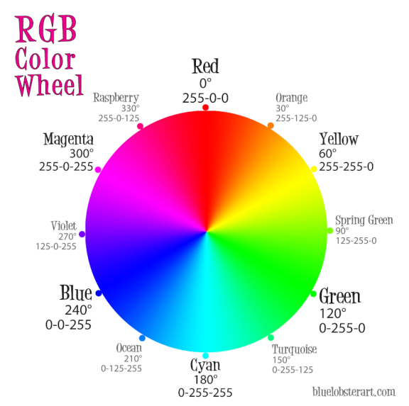
A small project
As a small project, we are going to combine the reading of the ADC and the control of the rgb LED ring. As we saw, the ADC delivers values between 0 and 4095 (12 bits). We can divide this range in 7 slices, corresponding to the 7 LEDs in the ring. For the lowest slice, the top LED will be lit. Then we go clockwise around the ring: the next LED lit will be to the right of the first one. For the highest slice, the middle LED will be lit. In a first version, write a program that prints the LED number corresponding to the signal level on the slider. Make sure you get a value between 0 and 7. Then light the LED you found with a single color (e.g. green) Very often, the color indicates the signal level: For low signal levels, we use "cold" colors (blue, cyan) for higher levels we use "hot" colors (magenta, red, white). The color for the top LED will therefore be blue, the color for the middle LED will be white. Here is the color sequence:| LED number | color | |
|---|---|---|
| 1 | blue | (0,0,31) |
| 2 | cyan | (0,31,31) |
| 3 | green | find the |
| 4 | yellow | other |
| 5 | magenta | colors |
| 6 | red | yourself |
| 0 | white |
Comments
| I | Attachment | History | Action | Size | Date | Who | Comment |
|---|---|---|---|---|---|---|---|
| |
exercises.odt | r3 r2 r1 | manage | 558.2 K | 2022-11-14 - 15:56 | UliRaich | |
| |
gnuplot_sin.png | r1 | manage | 29.9 K | 2022-10-15 - 20:47 | UliRaich | |
| |
helloWorld.png | r1 | manage | 71.5 K | 2022-10-15 - 13:55 | UliRaich | |
| |
led_color_wheel.png | r1 | manage | 165.2 K | 2022-10-24 - 16:48 | UliRaich | |
| |
trajectories.png | r1 | manage | 57.5 K | 2022-10-22 - 13:36 | UliRaich | |
| |
trajectories_V2.png | r2 r1 | manage | 67.4 K | 2022-11-14 - 15:29 | UliRaich |
This topic: AFNOG > ASP2022 > ExerciseSheets
Topic revision: r14 - 2022-11-14 - UliRaich
Ideas, requests, problems regarding TWiki? Send feedback

