

| I | Attachment | History | Action | Size | Date | Who | Comment |
|---|---|---|---|---|---|---|---|
| |
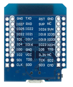
esp32_back.png | r1 | manage | 165.4 K | 2022-10-16 - 10:03 | UliRaich | |
| |
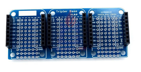
tripleBase.png | r1 | manage | 196.1 K | 2022-10-16 - 09:59 | UliRaich |
This topic: AFNOG > ASP2022 > MinimalLectures > HardwareAccessGPIO
Topic revision: r2 - 2022-10-16 - UliRaich
Ideas, requests, problems regarding TWiki? Send feedback