

| I | Attachment | History | Action | Size | Date | Who | Comment |
|---|---|---|---|---|---|---|---|
| |
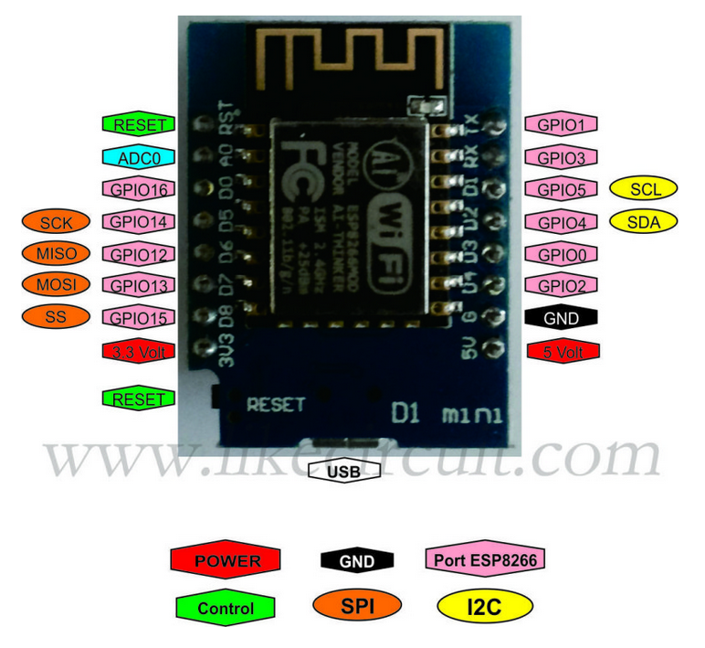
d1MiniPinout.png | r1 | manage | 542.9 K | 2019-03-20 - 09:27 | UliRaich | |
| |
wemosd1mini.png | r1 | manage | 313.5 K | 2019-03-20 - 09:20 | UliRaich |
This topic: AFNOG > WebHome > AFNOGWorkshop2019 > WeMosD1Mini
Topic revision: r6 - 2019-05-01 - UliRaich
Ideas, requests, problems regarding TWiki? Send feedback