%SLIDESHOWSTART%
Stepping Motors
Lecture 9
Uli Raich
UCC semester 2017/2018
The 27BJY-48 stepper motor and its ULN-2803 driver module

A lecture on youtube
There is an excellent
lecture describing the usage of exactly our stepper motor setup on youtube
Stepping Motors versus DC Motors
While DC motors simply spin when they are powered,
stepping motors can be moved in defined steps and thus positioned very precisely.
They contain 2 coils which can be powered in positive or negative
direction making the current flow in normal or reverse direction
and thus creating magnetic fields of opposite polarity
The rotor has a series of magnets (16 in case of the 28BYJ-48 which we are using)
with alternating opposite polarization.
A north pole followed by a south pole followed by a north pole and so on.
The motor base has 2*16 teeth which can be polarized as
north or south poles depending on the direction of the coil current.
Here is the data sheet of the
28BYJ-48
The Driver Card
The maximum current that a GPIO pin on the Raspberry Pi can deliver is 60 mA
which is insufficient to power the motor coils.
We therefore need a driver circuit (Darlington stage) to amplify
this current. In our case we use the
ULN-2803 chip
The little PCB has 4 LEDs on it to show which of the 2 coils is
powered and in which direction. This is very useful to demonstrate which signals
are sent to the motor and it illustrates nicely the functioning of the motor.
Connecting the Driver to the Motor

We can see from the connections that when powering the pink line
the coil current is flowing in one direction while when
powering the orange line it is flowing in the opposite direction
Motor Movement
First we power the first coil in such a way the the first tooth has a
south pole and the second one a north pole, which
makes the rotor (whose north magnet is considered) moves to the first tooth.
Then we switch off the first coil and power the second coil such that
the first tooth of the lower row has a south pole.
This makes the rotor move to this tooth.
Now switch off the second coil and switch the first one on again,
however this time with reverse current. The second tooth of the
upper row now has the south pole
(the poles are inversed with respect to the first step).
Now we switch on only the second coil with inverse current to make
the rotor move to the forth tooth. From now on the whole cycle repeats.
Signal Table for Single Phase Forward
We have seen in the last slide how we have to power the coils to
make the stepping motor move by 1 cycle, which is 4 steps in case of
Single Phase Forward stepping
How does this translate into a program?
We connect the 4 phases (coil 1 forward, coil 2 backward, coil 1 backward, coil 2 forward)
to 4 GPIO pins on the Raspberry Pi cobbler
Then we create the following signal table, which is a 2-dimensional array of booleans:

Sending the pulses to the hardware
Now all we have to do is to go through this table and, for each step,
send a high level to the GPIO pin to which we connected the coils.

Going through one step cycle

Other modes of operation
Single Step forward (and backward) works fine but we can do better.
Up to now we have always powered only one coil at a time.
It is however possible to power both coils at the same time.
This will draw of course more current but the motor will get
a higher torque and can therefore handle bigger loads.
Movement Double Phase Forward
Double Step Forward Table
Of course our signal table must change correspondingly,
our program to send out the signals for one full cycle stays the same however.

Programming double step forward mode
For this, nothing much is to be said:
We change the table, but since the program is independent
from the contents of the stepping table, the code stays strictly the same
Position of rotor in doubleStepForward mode
An important point to note is that the rotor moves half a step
further than in single Step Forward because its north pole
is now attracted by the top and the bottom south poles.
By first powering only the upper coil, then powering both coils
then powering again only one pole of the lower coil it should
be possible to move the motor by half steps only
and by doing so increase its resolution.
This is what we call half step mode and it is a combination
of single and double step forward modes.
The torque of the motor is less than in double step forward
and the speed is only about half because now we need 8 steps for a full cycle.
Movement Half Step Forward
Half Step Forward Table

Programming Half Step Mode
Again, apart from the fact that we must now pass through
a table of 8 entries instead of 4 the program does not change.
If we use the signature of all bits being zero
as end of table indicator then no change at all is required.
The pigpio library
Up to now we always used wiringPi to access our GPIO pins.
I explained in the first lecture on the Raspberry Pi
that there are 2 independent libraries available:
Why would we be interested to use a different library?
Advantages of pigpio
The pigpio library comes in 2 versions:
- The standard one where calls to the library code
results in direct access to the hardware
- The daemon version where first a daemon (pigpiod)
is started and then the hardware access is only made in this daemon
Accessing the daemon
The daamon is started once before we make any hardware access:
sudo pigpiod
After this all hardware access can be make by a normal user
The program communicates with the deamon through library calls
which connect to the daemon through
- pipes (when running on the Raspberry Pi) or
- through sockets when running on a remote system
like our Ubuntu PC
There is a library version that runs on the PC
We can write C programs on the PC with hardware access
to our devices on the bread board through pigpio calls to the
PC version of the library which communicates
with the pigpio daemon on the Raspberry Pi
Documentation of pigpio
%SLIDESHOWSTART%
Stepping Motors
Lecture 9
Uli Raich
UCC semester 2017/2018
The 27BJY-48 stepper motor and its ULN-2803 driver module
Stepping Motors versus DC Motors
While DC motors simply spin when they are powered,
stepping motors can be moved in defined steps and thus positioned very precisely.
They contain 2 coils which can be powered in positive or negative
direction making the current flow in normal or reverse direction
and thus creating magnetic fields of opposite polarity
The rotor has a series of magnets (16 in case of the 28BYJ-48 which we are using)
with alternating opposite polarization.
A north pole followed by a south pole followed by a north pole and so on.
The motor base has 2*16 teeth which can be polarized as
north or south poles depending on the direction of the coil current.
Here is the data sheet of the
28BYJ-48
The Driver Card
The maximum current that a GPIO pin on the Raspberry Pi can deliver is 60 mA
which is insufficient to power the motor coils.
We therefore need a driver circuit (Darlington stage) to amplify
this current. In our case we use the
ULN-2803 chip
The little PCB has 4 LEDs on it to show which of the 2 coils is
powered and in which direction. This is very useful to demonstrate which signals
are sent to the motor and it illustrates nicely the functioning of the motor.
Connecting the Driver to the Motor
We can see from the connections that when powering the pink line
the coil current is flowing in one direction while when
powering the orange line it is flowing in the opposite direction
Motor Movement
First we power the first coil in such a way the the first tooth has a
south pole and the second one a north pole, which
makes the rotor (whose north magnet is considered) moves to the first tooth.
Then we switch off the first coil and power the second coil such that
the first tooth of the lower row has a south pole.
This makes the rotor move to this tooth.
Now switch off the second coil and switch the first one on again,
however this time with reverse current. The second tooth of the
upper row now has the south pole
(the poles are inversed with respect to the first step).
Now we switch on only the second coil with inverse current to make
the rotor move to the forth tooth. From now on the whole cycle repeats.
Signal Table for Single Phase Forward
We have seen in the last slide how we have to power the coils to
make the stepping motor move by 1 cycle, which is 4 steps in case of
Single Phase Forward stepping
How does this translate into a program?
We connect the 4 phases (coil 1 forward, coil 2 backward, coil 1 backward, coil 2 forward)
to 4 GPIO pins on the Raspberry Pi cobbler
Then we create the following signal table, which is a 2-dimensional array of booleans:
Sending the pulses to the hardware
Now all we have to do is to go through this table and, for each step,
send a high level to the GPIO pin to which we connected the coils.
Going through one step cycle
Other modes of operation
Single Step forward (and backward) works fine but we can do better.
Up to now we have always powered only one coil at a time.
It is however possible to power both coils at the same time.
This will draw of course more current but the motor will get
a higher torque and can therefore handle bigger loads.
Movement Double Phase Forward
Double Step Forward Table
Of course our signal table must change correspondingly,
our program to send out the signals for one full cycle stays the same however.
Programming double step forward mode
For this, nothing much is to be said:
We change the table, but since the program is independent
from the contents of the stepping table, the code stays strictly the same
Position of rotor in doubleStepForward mode
An important point to note is that the rotor moves half a step
further than in single Step Forward because its north pole
is now attracted by the top and the bottom south poles.
By first powering only the upper coil, then powering both coils
then powering again only one pole of the lower coil it should
be possible to move the motor by half steps only
and by doing so increase its resolution.
This is what we call half step mode and it is a combination
of single and double step forward modes.
The torque of the motor is less than in double step forward
and the speed is only about half because now we need 8 steps for a full cycle.
Movement Half Step Forward
Half Step Forward Table
Programming Half Step Mode
Again, apart from the fact that we must now pass through
a table of 8 entries instead of 4 the program does not change.
If we use the signature of all bits being zero
as end of table indicator then no change at all is required.
The pigpio library
Up to now we always used wiringPi to access our GPIO pins.
I explained in the first lecture on the Raspberry Pi
that there are 2 independent libraries available:
Why would we be interested to use a different library?
Advantages of pigpio
The pigpio library comes in 2 versions:
- The standard one where calls to the library code
results in direct access to the hardware
- The daemon version where first a daemon (pigpiod)
is started and then the hardware access is only made in this daemon
Accessing the daemon
The daamon is started once before we make any hardware access:
sudo pigpiod
After this all hardware access can be make by a normal user
The program communicates with the deamon through library calls
which connect to the daemon through
- pipes (when running on the Raspberry Pi) or
- through sockets when running on a remote system
like our Ubuntu PC
There is a library version that runs on the PC
We can write C programs on the PC with hardware access
to our devices on the bread board through pigpio calls to the
PC version of the library which communicates
with the pigpio daemon on the Raspberry Pi
Documentation of pigpio
%SLIDESHOWEND%
--

Slide 1: Stepping Motors
Lecture 9
Uli Raich
UCC semester 2017/2018
Slide 2: The 27BJY-48 stepper motor and its ULN-2803 driver module
Slide 3: Stepping Motors versus DC Motors
While DC motors simply spin when they are powered,
stepping motors can be moved in defined steps and thus positioned very precisely.
They contain 2 coils which can be powered in positive or negative
direction making the current flow in normal or reverse direction
and thus creating magnetic fields of opposite polarity
The rotor has a series of magnets (16 in case of the 28BYJ-48 which we are using)
with alternating opposite polarization.
A north pole followed by a south pole followed by a north pole and so on.
The motor base has 2*16 teeth which can be polarized as
north or south poles depending on the direction of the coil current.
Here is the data sheet of the
28BYJ-48
Slide 4: The Driver Card
The maximum current that a GPIO pin on the Raspberry Pi can deliver is 60 mA
which is insufficient to power the motor coils.
We therefore need a driver circuit (Darlington stage) to amplify
this current. In our case we use the
ULN-2803 chip
The little PCB has 4 LEDs on it to show which of the 2 coils is
powered and in which direction. This is very useful to demonstrate which signals
are sent to the motor and it illustrates nicely the functioning of the motor.
Slide 5: Connecting the Driver to the Motor
We can see from the connections that when powering the pink line
the coil current is flowing in one direction while when
powering the orange line it is flowing in the opposite direction
Slide 6: Motor Movement
First we power the first coil in such a way the the first tooth has a
south pole and the second one a north pole, which
makes the rotor (whose north magnet is considered) moves to the first tooth.
Then we switch off the first coil and power the second coil such that
the first tooth of the lower row has a south pole.
This makes the rotor move to this tooth.
Now switch off the second coil and switch the first one on again,
however this time with reverse current. The second tooth of the
upper row now has the south pole
(the poles are inversed with respect to the first step).
Now we switch on only the second coil with inverse current to make
the rotor move to the forth tooth. From now on the whole cycle repeats.
Slide 7: Signal Table for Single Phase Forward
We have seen in the last slide how we have to power the coils to
make the stepping motor move by 1 cycle, which is 4 steps in case of
Single Phase Forward stepping
How does this translate into a program?
We connect the 4 phases (coil 1 forward, coil 2 backward, coil 1 backward, coil 2 forward)
to 4 GPIO pins on the Raspberry Pi cobbler
Then we create the following signal table, which is a 2-dimensional array of booleans:
Slide 8: Other modes of operation
Single Step forward (and backward) works fine but we can do better.
Up to now we have always powered only one coil at a time.
It is however possible to power both coils at the same time.
This will draw of course more current but the motor will get
a higher torque and can therefore handle bigger loads.
Slide 9: Movement Double Phase Forward
Slide 10: Double Step Forward Table
Of course our signal table must change correspondingly,
our program to send out the signals for one full cycle stays the same however.
Slide 11: Programming double step forward mode
For this, nothing much is to be said:
We change the table, but since the program is independent
from the contents of the stepping table, the code stays strictly the same
Slide 12: Position of rotor in doubleStepForward mode
An important point to note is that the rotor moves half a step
further than in single Step Forward because its north pole
is now attracted by the top and the bottom south poles.
By first powering only the upper coil, then powering both coils
then powering again only one pole of the lower coil it should
be possible to move the motor by half steps only
and by doing so increase its resolution.
This is what we call half step mode and it is a combination
of single and double step forward modes.
The torque of the motor is less than in double step forward
and the speed is only about half because now we need 8 steps for a full cycle.
Slide 13: Movement Half Step Forward
Slide 14: Half Step Forward Table
Slide 15: Programming Half Step Mode
Again, apart from the fact that we must now pass through
a table of 8 entries instead of 4 the program does not change.
If we use the signature of all bits being zero
as end of table indicator then no change at all is required.
Slide 16: The pigpio library
Up to now we always used wiringPi to access our GPIO pins.
I explained in the first lecture on the Raspberry Pi
that there are 2 independent libraries available:
Why would we be interested to use a different library?
Slide 17: Advantages of pigpio
The pigpio library comes in 2 versions:
- The standard one where calls to the library code
results in direct access to the hardware
- The daemon version where first a daemon (pigpiod)
is started and then the hardware access is only made in this daemon
Slide 18: Accessing the daemon
The daamon is started once before we make any hardware access:
sudo pigpiod
After this all hardware access can be make by a normal user
The program communicates with the deamon through library calls
which connect to the daemon through
- pipes (when running on the Raspberry Pi) or
- through sockets when running on a remote system
like our Ubuntu PC
There is a library version that runs on the PC
We can write C programs on the PC with hardware access
to our devices on the bread board through pigpio calls to the
PC version of the library which communicates
with the pigpio daemon on the Raspberry Pi
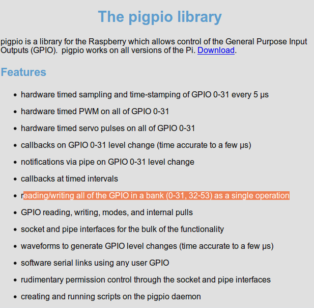
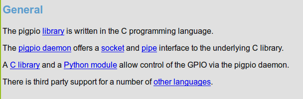
Slide 19: Documentation of pigpio
The WEB page of pigpio can be found
here

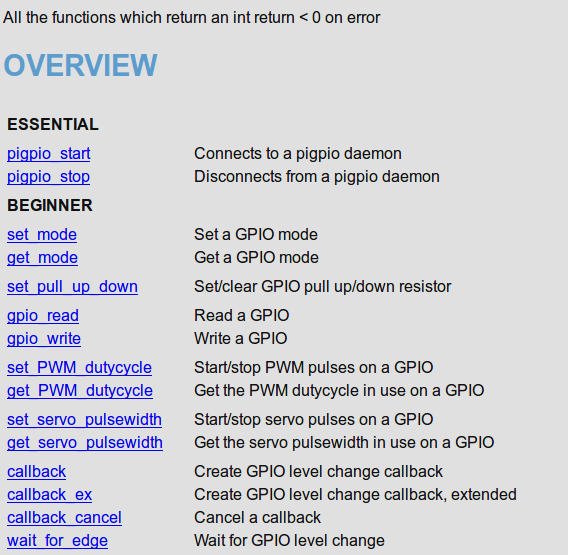
Slide 20: Features of pigpio

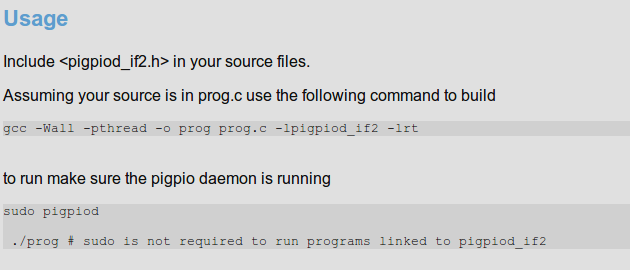
Slide 21: This is how to use the library

Please convert this to what will be required in your source code.
Slide 22: Sending the pulses to the hardware
Now all we have to do is to go through this table and, for each step,
send a high level to the GPIO pin to which we connected the coils.
Slide 23: Going through one step cycle
--
 Uli Raich - 2017-10-16
Comments
The WEB page of pigpio can be found here


