Interfacing Scilab to the Raspberry Pi or the Arduino
Introduction
Scilab![]() is a system for open source program for numerical mathematics quite similar to Matlab even though the Scilab programming language is not compatible to the Matlab language. Scilab exists for Windows, Linux and Mac OS X and is used by many universities around the world.Scilab's equivalent to Matlab's Simulink is called Xcos allowing to create simulations through a drag and drop interface.
is a system for open source program for numerical mathematics quite similar to Matlab even though the Scilab programming language is not compatible to the Matlab language. Scilab exists for Windows, Linux and Mac OS X and is used by many universities around the world.Scilab's equivalent to Matlab's Simulink is called Xcos allowing to create simulations through a drag and drop interface.
The goal of these pages is to create an Xcos interface to the Raspberry Pi and to the Arduino in such a way that access to sensor readout or actuator control is given through drag and drop. This requires the programming of the required Xcos blocks and a server program communicating with these blocks through either a socket interface in the case of the Raspberry Pi or through serial communication in case of the Arduino.
As with many open source projects the weakest point of Scilab is its documentation. For this reason I try to document my approach to the problem in these pages.
Installation and first steps
In order to get some feeling on how Scilab works I first collected as much information as possible on the system and then tried to install it on my Ubuntu 18.04 system.
- The main page: scilab.org
 . From here you can download and install the newest version: scilab-6.0.1. Even though apt packages exist for Scilab on Ubuntu-18.04, these packages are broken and you better install it from the .tar.gz packages.
- When trying some tutorials I saw problems with this newest version and I therefore installed the former stable version: scilab-5.5.2. Here is a description of how to do this.
- I also downloaded the scilab sources from github but did not manage to compile. This is the error I get even though jogl2 is installed on my system. To be examined...

Concerning tutorials:
- The best place to start out is https://www.scilab.org/tutorials
- Another site with a lot of tutorials you find at http://www.openeering.com/scilab_tutorials
- Even if the title of this tutorial is " Scilab for real dummies" I don't think it "real dummies" will manage to work with it. The manual is written in form of slides and there are 504 such slides. I was attracted be the title because I did not consider myself an expert on mathematical simulation programs and I went through the tutorial from page 1 to the last page and I tried all of the examples. The example code is attached to this TWiki page
- An Introduction to Scilab 5.5.2 and Xcos by Antonelli and Chiaverini (in italian)
- Eine Einführung in Scilab by Bruno Pincon is written in German.
To become acquainted with the Scilab language I propose to go through the tutorials for dummies first and try the examples.
Wetting the appetite
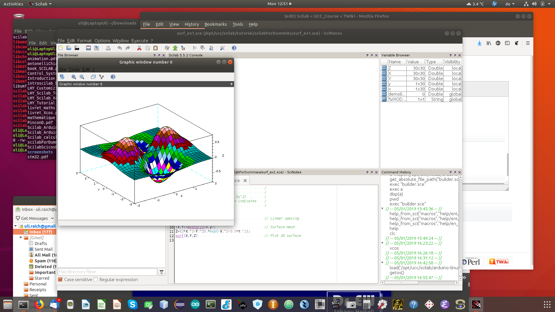
To make you interested in the system I show you a few plots extracted from the tutorial for dummies. They show:
- a few colored sectors
- Bode plots of an RC circuit
- a surface plot
- some histograms
 |
 |
 |
 |

Xcos
The Scilab equivalent to Simulink is called Xcos. This is a drap and drop interface to Scilab which allows to create simulation without any program by just graphically connecting blocks of predefined code. The goal of this project is to create Xcos blocks in such a way that data from sensors connected to a Raspberry Pi or an Arduino can be imported in real time into Scilab / Xcos and treated or plotted there. Of course this requires some connection, through sockets in the case of the Raspberry Pi or through a serial line in case of the Arduino.
The following screen dump shows an Xcos diagram for a blinking LED on the Arduino.

The block with the Arduino icon allows to configure the serial port to be used for communication. The second block on the top row is used to define the duration of data taking and the sampling frequency.
The pulse generator on the bottom left will define how long the LED will be switched on and off and the Digital Write block will transmit this information to the Arduino which will perform the hardware access and switch the LED on or off through GPIO line 13, which is the default GPIO line for the builtin LED on an Arduino Uno or Nano. The pin number can be changed by double clicking on the block.
Finally the oscilloscope block will display the signal sent to the Arduino.
Implementing the Arduino toolbox
Comments


| I |
Attachment | History | Action | Size | Date | Who | Comment |
|---|---|---|---|---|---|---|---|
| |
scilabForDummies.tar.gz | r1 | manage | 16.2 K | 2019-01-07 - 11:34 | UliRaich | |
| |
arduinoXcos.png | r1 | manage | 35.6 K | 2019-01-07 - 12:13 | UliRaich | |
| |
bode.png | r1 | manage | 26.6 K | 2019-01-07 - 11:56 | UliRaich | |
| |
gui.png | r1 | manage | 38.5 K | 2019-01-07 - 12:00 | UliRaich | |
| |
histograms.png | r1 | manage | 25.8 K | 2019-01-07 - 11:56 | UliRaich | |
| |
scilabCompile.png | r1 | manage | 15.2 K | 2019-01-07 - 11:34 | UliRaich | |
| |
sectors.png | r1 | manage | 20.4 K | 2019-01-07 - 11:56 | UliRaich | |
| |
surface.png | r2 r1 | manage | 35.1 K | 2019-01-07 - 12:00 | UliRaich |

Ideas, requests, problems regarding TWiki? Send feedback