Difference: MinimalLectures (2 vs. 3)
Revision 32022-10-15 - UliRaich
| Line: 1 to 1 | ||||||||
|---|---|---|---|---|---|---|---|---|
Lecture notes | ||||||||
| Added: | ||||||||
| > > | Summary:
| |||||||
IntroductionDuring the exercise sessions, we will first develop a program that lights the user programmable LED on the CPU card. This displays a binary signal, which can only be high or low. The exercise therefore demonstrates how to output a signal and how to control a single digital signal line. | ||||||||
| Line: 16 to 21 | ||||||||
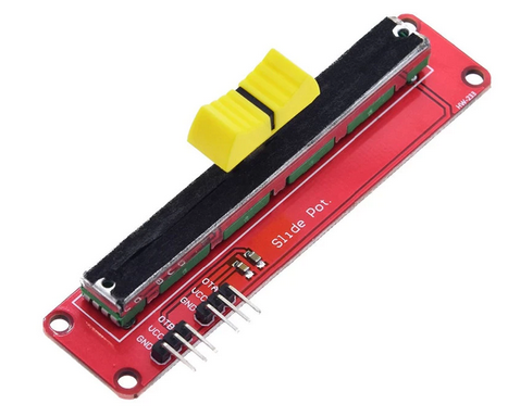
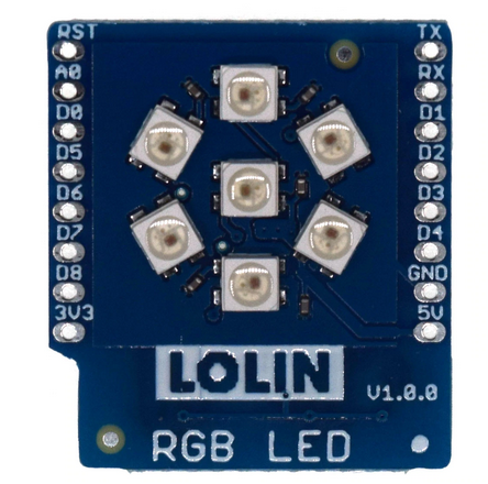
A slightly more complex program will allow us to read the signal level generated by an analogue sensor (our potentiometer) and display the signal level on the 7 LED rgb (red, green, blue) display. For this to work, we must first understand how to connect and read the analogue signal using the Analogue to Digital Converter (ADC). Then we must find out how an LED on the LED ring can be lit and how to select its color. Finally, we can again combine the two functions into a single program. This will read the signal level from the potentiometer and light one of the LEDs on the LED ring. For lowest signal levels, the top LED is lit in blue (which often represents a cold or low value). If the value is a bit higher, then the second LED is activated in cyan, After that we go clockwise using the colors (blue, cyan, green, yellow, magenta, red, white) where white will be displayed for the highest signal level on the center LED.
| ||||||||
| Changed: | ||||||||
| < < | Now that we know what we have to do, let's go for it! Programming Python | |||||||
| > > | Now that we know what we have to do, let's go for it! Communicating with the ESP32 | |||||||
|
- - | ||||||||
View topic | History: r10 < r9 < r8 < r7 | More topic actions...
Ideas, requests, problems regarding TWiki? Send feedback

