Difference: PCF8591 (3 vs. 4)
Revision 42017-02-05 - uli
| Line: 1 to 1 | ||||||||
|---|---|---|---|---|---|---|---|---|
Analogue to Digital and Digital to Analogue Conversion | ||||||||
| Line: 11 to 11 | ||||||||
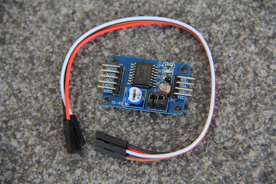
| There are 2 LEDs on the PCB: a red one showing that the board is powered and a green one connected to the DAC output. | ||||||||
| Changed: | ||||||||
| < < | I used the forth channel to feed back the DAC output. | |||||||
| > > | I used the free channel to feed back the DAC output. | |||||||
| ||||||||
View topic | History: r4 < r3 < r2 < r1 | More topic actions...
Ideas, requests, problems regarding TWiki? Send feedback

