| |
| META TOPICPARENT |
name="WebHome" |
Solutions to the exercises |
| |
- Solutions to exercise 13: the ds1307 Real Time Clock
These solutions show how to set the real time clock using a complex command line argument interface with getopt_long. Many of the Linux commands are implemented this way. The program, when called without parameters, shows the current date and time, with parameters it allows to set seconds, minutes, hours, day...
https://iotworkshop.africa/pub/Embedded_Systems/SolutionsToTheExercises/rtc.tar.gz |
|
<
< |
- Solutions to exercise 9: the at24c32 EEPROM
We have a little PCB with a ds1307 Real Time Clock and an at24c32 32kbit EEPROM on board. Both devices can be accessed through the I2C bus. These solutions show what needs to be done to read and write the EEPROM. Again the access routines are implemented in a shared library. In this code we do not use pigpio library calls for I2C access but use the device driver implemented for the Linux kernel directly.
|
>
> |
- Solutions to exercise 9: the at24c32 EEPROM
We have a little PCB with a ds1307 Real Time Clock and an at24c32 32kbit EEPROM on board. Both devices can be accessed through the I2C bus. These solutions show what needs to be done to read and write the EEPROM. Again the access routines are implemented in a shared library. In this code we do not use pigpio library calls for I2C access but use the device driver implemented for the Linux kernel directly.
- Solutions to exercise 20: The Heart Rate Monitor
When trying the LED blink program I was first surprised that the blinking did not work and found out only that that this is because on infrared is employed on the board. Using infrared light has the advantage that visible light from the environment does not disturb the measurement.
In order to find out find the system works well, I measured the voltage at the output or the photo diode with a multimeter when blinking the diode with a low (2 HZ) frequency.
Once this worked fine I just had to connect the diode output to a free input of an ADC and the PCF8591 is good enough.
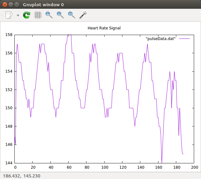
The code is attached and here is a plot of the results:

https://iotworkshop.africa/pub/Embedded_Systems/SolutionsToTheExercises/heartbeat.tar.gz |
| | --  Uli Raich - 2017-10-14 Uli Raich - 2017-10-14
Comments |
| |
| META FILEATTACHMENT |
attachment="dht11.tar.gz" attr="" comment="" date="1510478831" name="dht11.tar.gz" path="dht11.tar.gz" size="1591102" user="uli" version="1" |
| META FILEATTACHMENT |
attachment="hd44780.tar.gz" attr="" comment="" date="1510479190" name="hd44780.tar.gz" path="hd44780.tar.gz" size="262161" user="uli" version="1" |
| META FILEATTACHMENT |
attachment="pcf8591.tar.gz" attr="" comment="" date="1510587236" name="pcf8591.tar.gz" path="pcf8591.tar.gz" size="1814" user="uli" version="1" |
|
|
>
> |
| META FILEATTACHMENT |
attachment="heartbeat.tar.gz" attr="" comment="" date="1510672452" name="heartbeat.tar.gz" path="heartbeat.tar.gz" size="56097" user="uli" version="1" |
| META FILEATTACHMENT |
attachment="heartBeat.png" attr="" comment="" date="1510672452" name="heartBeat.png" path="heartBeat.png" size="46220" user="uli" version="1" |
|

