Solutions to the exercises
This is the page to which the solutions will be uploaded. These will mainly consist of gzipped tar files which you can download and unpack. Several of the solution packages contain shared libraries the students can use. The idea is to give them a feeling for how the sensors work, before they try to write programs to access the sensor registers by themselves. Of course libraries hide many of the difficult intricacies to give users easy access to most (but usually not all) of the sensor's functionality.The libraries usually come in 2 files:
- an include file
- the share library binary itself
- -I/opt/ucc/include in its CFLAGS
- -L/opt/ucc/lib in its LDFLAGS
- -ldht11, if we use the libdht11.so library, otherwise replace dht11 by the name of your library
- setup the LD_LIBRARY_PATH to include /opt/ucc/lib
export LD_LIBRARY_PATH=$LD_LIBRARY_PATH:/opt/ucc/lib, prior to running the program - create a file ucc.conf with only the text "/opt/ucc/lib" in it and save it in /etc/ld.so.conf.d
Then run ldconfig. This will include /opt/ucc/lib into the system wide search path for shared libraries
- Solutions to exercise 1: Linux Commands
There are no solutions to this exercise. We simply try out a series of bash commands
- Solutions to exercise 2: C programming:
These are only the solutions to the exercises. Many more small example programs you find in the lecture page
Lecture3: Introduction to C Programming
- Solutions to exercise 3: Programming Tools
Even though there are no solutions to exercise3: Compilations Tools, here are a few Makefile examples nevertheless:
- Solutions to the exercises on files, pipes and sockets
These exercises have been skipped but I attach the solution codes nevertheless such that you can have a look at them and/or use them in a future course
- Solutions to exercise 4: Raspberry Pi
There are no solutions to this exercise session because we only use programs that have already been written before.
- Solutions to exercise 5: LED
For the mygpio program, these are the tests you must perform in order to make the program safe against wrong input from the user- test if the user has given at least 2 arguments namely a string, which should be "read" or "write" and the pin number
(argv may not be smaller than 3) - check if argv[1] is either "read" or "write". Use strcmp to accomplish this
- if argv[1] is "read", make sure argc is exactly 3
- if argv[1] is "write", make sure argc is exactly 4
- convert the pin number from string to integer. You may be tempted to use atoi() but you must not, because atoi() does not check for conversion errors. Use strtol() instead.
- Make sure the converted pin number is in the range 0..7
For the "read" case we are done with our checks here - for the "write" case convert the logic level and make sure you get either 0 or 1
- test if the user has given at least 2 arguments namely a string, which should be "read" or "write" and the pin number
In addition to the solutions on the Raspberry Pi I wrote a simple Qt GUI: https://iotworkshop.africa/pub/Embedded_Systems/SolutionsToTheExercises/QtLED.tar.gz One way to develop the course in the future is the replacement of the C programming language by Python. Many Python modules are available for the Raspberry Pi and its sensors but in a course like ours it would be interesting to look behind the facade of prefabricated modules and try to write those ourselves to be able to understand what is going one behind the scene. This will allow us to create Python modules also for those devices which do not have a Python module written by somebody else yet. Here is an attempt to write the LED exercises in Python: https://iotworkshop.africa/pub/Embedded_Systems/SolutionsToTheExercises/ledPython
- Solutions to the exercises on switches
These exercises have also been skipped because of lack of time but I attach the solution codes nevertheless such that you can have a look at them and/or use them in a future course
- Solutions to exercise 7: Stepping Motors
This one is for the lecturers only:
When working with pigpio via the pigpiod daemon, the daemon most first be started be the super user.
If you do not want to give root access to your students (which you probably don't want as long as they do not really know what they are doing) you may start the daemon at system startup:
- Copy the pigpiod startup script ( https://iotworkshop.africa/pub/Embedded_Systems/SolutionsToTheExercises/pigpiod )to /etc/init.d
- chmod 755 /etc/init.d/pigpiod
- update-rc.d pigpiod defaults
- update-rc.d pigpiod enable
In addition to the solutions to the stepping motor exercises I add the code written for the rotary encoder, which is a sort of a reverse stepping motor. Instead of sending a pulse sequence, you receive one and by interpreting it you can tell the relative angle the motor has reached. Here is the code: https://iotworkshop.africa/pub/Embedded_Systems/SolutionsToTheExercises/stepper.tar.gz https://iotworkshop.africa/pub/Embedded_Systems/SolutionsToTheExercises/rotaryEncoder.tar.gz
- Solutions to the exercises on the DS18B20 1-wire digital temperature sensor
The solutions make use of the device driver available for the DS18B20 in the Linux system. Since we had no time to look into the concepts of device drivers, this exercise has been left out. Here are the solutions, if you want to try for a future course:
- Solutions to exercise 6: The DHT11 temperature and humidity sensor
The code contains an example of how to write a shared library. You can collect all libraries for your course in a common directory (.g. /opt/ucc/lib) as you do for all corresponding include files (/opt/ucc/include). Then you make the directory of libraries globally known to the system by putting a file ucc.conf into /etc/ld.so.conf. ucc.conf simply contains the text /opt/ucc/lib. Finally you run the command sudo ldconf and /opt/ucc/lib will be added to the search path of shared libraries on the system.
- Solutions to the exercises on light measurement
Again the exercises have not been proposed during the course. They use the photo resistor available in the sensor kit but need a high value capacitor in addition. In these exercise the analogue value of resistance is not measured through an ADC but uses a capacitor which is charged over the resistance in the photo resistor. By measuring the time the capacitor needs to be charge to a level that switches the state of a gpio pin from low to high, the resistance and thus the light intensity can be measured.
Again the solutions are available here:
- Solutions to exercise 12: Reading the BMP180 temperature and barometric pressure sensor
The manufacturer of the device provides an access library to the device which takes care of converting the raw data read from the sensor device into humanly readable values. The library must be adapted to the I2C access method used be the micro-controller to which the device is connected (in our case the Raspberry Pi). The solutions show how this is done, how to extract the documentation from the source code using the doxygen tool and how to use the library in your own programs.
- Solutions to exercise 10: a 2 line LCD Display
Very often embedded systems do not have a keyboard, mouse and screen attached to them but they must live with more rudimentary (and much cheaper) input/output devices. Such a device is the 2-line display we have in our sensor collection. It is highly recommendable to write a shared library for the device because it can be used in many applications (see the nameDisplay, VoltMeter and MeteoStation we had at the Open Day).
The solutions show how this is done, how the library is tested and how to include in-code documentation in doxygen format.
- Solutions to exercise 8: Digital to Analogue conversion
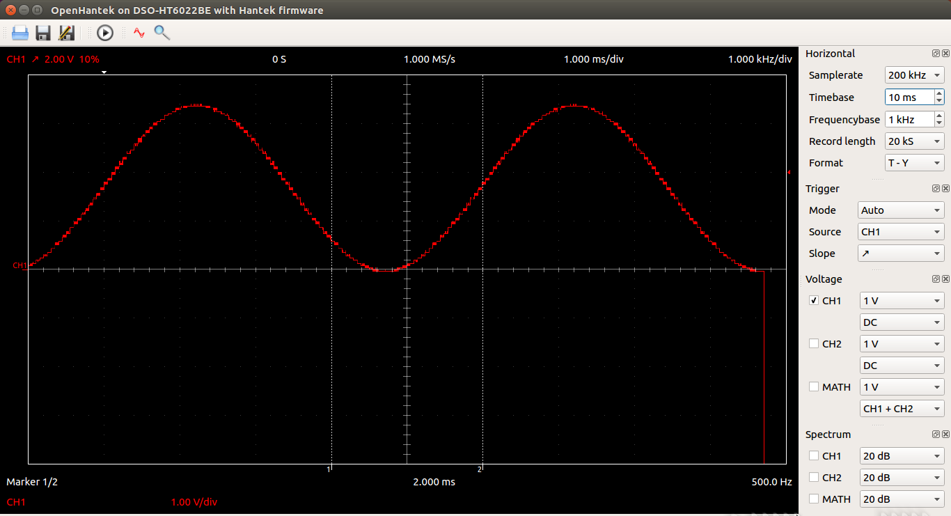
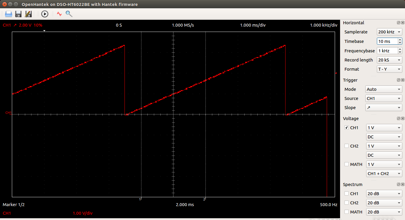
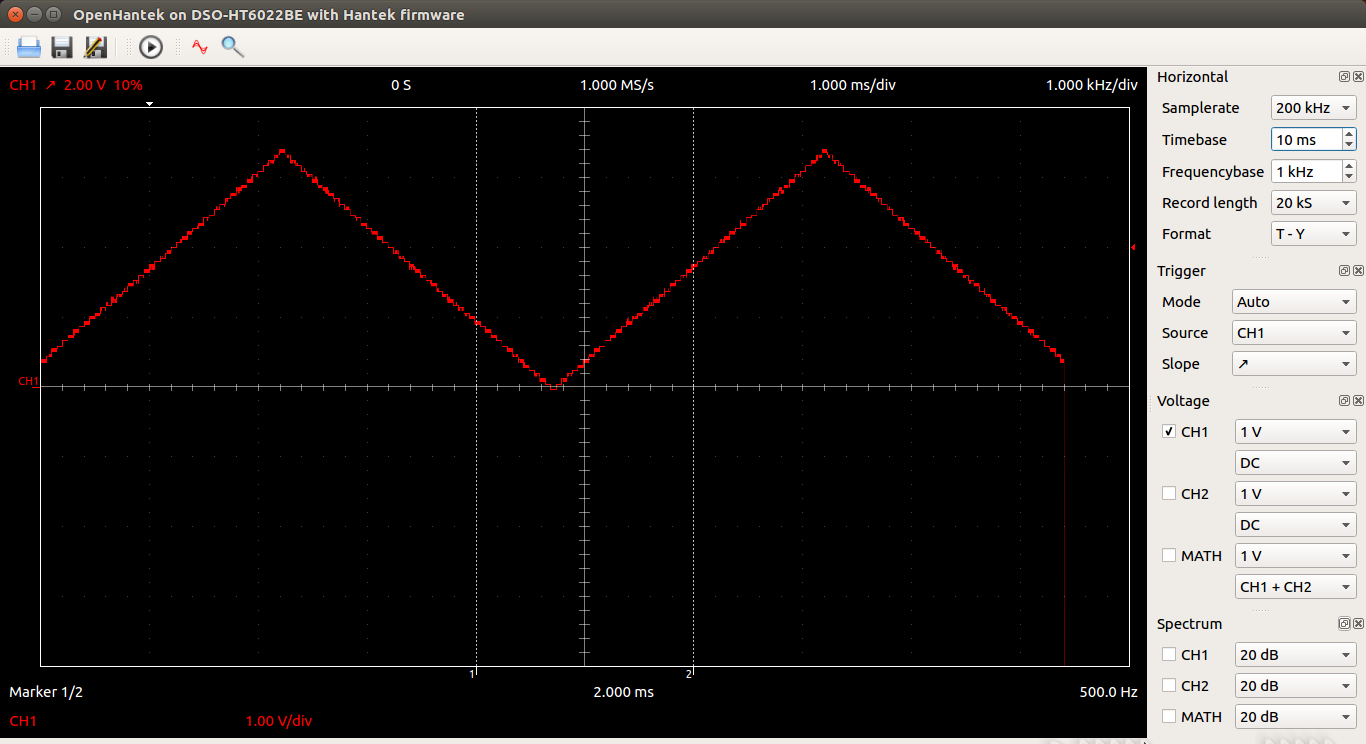
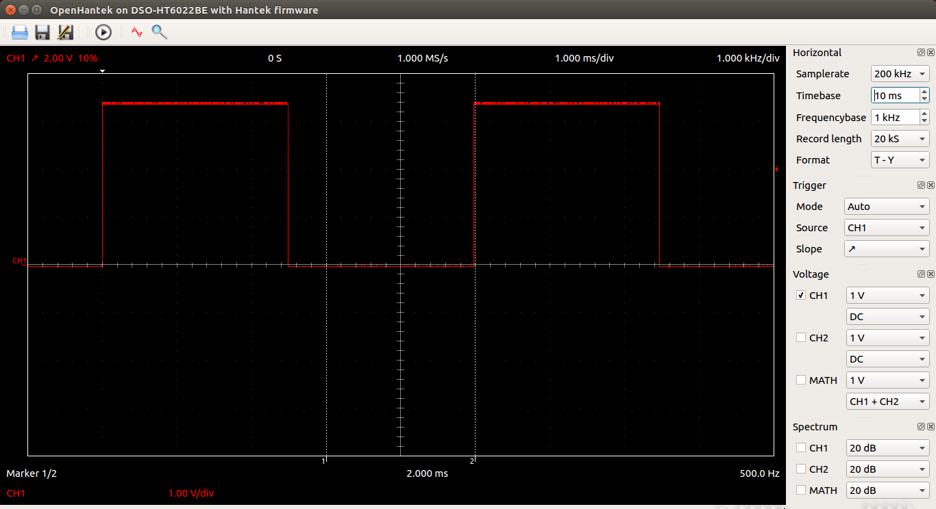
Many devices are controlled through analogue signal levels. A nice example of a device creating these signal levels is the MicroChip mcp4725, a 12 bit I2C based DAC. The solutions show examples of how to set a level and how to create wave forms.
https://iotworkshop.africa/pub/Embedded_Systems/SolutionsToTheExercises/mcp4725.tar.gz
The frequency of the wave form is limited by the I2C access speed (normally 100 kBit/s). The chip is capable of going up to 3.4 MBits/s. When measuring the time needed for a single I2C transfer I get 500 us for a "write" to the DAC. With 100 samples in the signal I therefore get a maximum frequency of
1/50*10e-3 = 200 Hz.
The I2C interface in the BCM2835 CPU chip on the Raspberry Pi can go up to almost 1.7 Mbps. I therefore need a library which allows me to control the corresponding register, which I found in the bcm2835 library
which however is much lower level than pigpio or wiringPi and therefore more difficult to understand and use.
The library code is attached to this page.
The Makefile for the library has been re-written to create a shared instead of a static library as done by the original code. When using this library instead of pigpio and setting the clock divider for the I2C bus to the highest speed possible I get an increase in frequency by a factor of 10 (60us per I2C transfer instead of 520 us) resulting in a max. frequencies of 2 KHz for a full 100 sample signal. Again the code is attached.
Here are some screen shots taken from the Hantek 6022BE oscilloscope equipped with far from perfect software. This software is however able to read out some wave forms and display them.
 |
 |
 |
 |
- Solutions to exercise 11: Analogue to Digital Conversion
Even more important than digital to analogue conversion is its counterpart: analogue to digital conversion (ADC). Even though we have a high precision 4 channel ADC in our kit of sensors (the ADS1115 16 bit ADC) we use the much simpler model: a PCF8591, 8 bit ADC, simply because the PCB on which this ADC is mounted, already contains a potentiometer, a photo resistor and a thermistor which which we can play.
When used in conjunction with the 2-line LCD display it is easy to create a simple volt meter.
- Solutions to exercise 13: the ds1307 Real Time Clock
These solutions show how to set the real time clock using a complex command line argument interface with getopt_long. Many of the Linux commands are implemented this way. The program, when called without parameters, shows the current date and time, with parameters it allows to set seconds, minutes, hours, day...
- Solutions to exercise 9: the at24c32 EEPROM
We have a little PCB with a ds1307 Real Time Clock and an at24c32 32kbit EEPROM on board. Both devices can be accessed through the I2C bus. These solutions show what needs to be done to read and write the EEPROM. Again the access routines are implemented in a shared library. In this code we do not use pigpio library calls for I2C access but use the device driver implemented for the Linux kernel directly.
However, a version of the library passing through pigpio is given also, as is a version of readEnigma making calls to pigpio instead of the at24c32 library.
- Solutions to exercise 20: The Heart Rate Monitor
When trying the LED blink program I was first surprised that the blinking did not work and found out only that that this is because on infrared is employed on the board. Using infrared light has the advantage that visible light from the environment does not disturb the measurement.
In order to find out find the system works well, I measured the voltage at the output or the photo diode with a multimeter when blinking the diode with a low (2 HZ) frequency.
Once this worked fine I just had to connect the diode output to a free input of an ADC and the PCF8591 is good enough.
The code is attached and here is a plot of the results: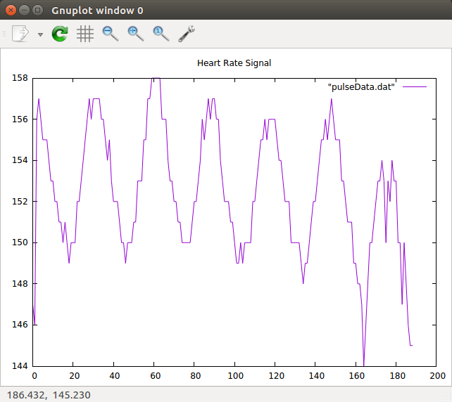
This works nicely on a white man's finger but the black skin of a black man's finger obscures the photo diode that much that the blood color cannot be measured, at least not with the PCF8591 ADC. We should try with the ADS1115 which may solve the problem because of its largely increased resolution.
Comments
| I | Attachment | History | Action | Size | Date | Who | Comment |
|---|---|---|---|---|---|---|---|
| |
QtLED.tar.gz | r1 | manage | 3245.2 K | 2017-11-08 - 18:23 | UnknownUser | |
| |
at24c32EEProm.tar.gz | r1 | manage | 0.1 K | 2017-12-12 - 08:33 | UnknownUser | |
| |
bcm2835-1.52.tar.gz | r1 | manage | 625.7 K | 2017-11-03 - 08:04 | UnknownUser | |
| |
bmp180.tar.gz | r1 | manage | 244.1 K | 2017-10-31 - 08:38 | UnknownUser | |
| |
communication.tar.gz | r1 | manage | 0.1 K | 2017-10-26 - 08:24 | UnknownUser | |
| |
dht11.tar.gz | r1 | manage | 1553.8 K | 2017-11-12 - 09:27 | UnknownUser | |
| |
ds18b20.tar.gz | r1 | manage | 20.9 K | 2017-10-31 - 08:10 | UnknownUser | |
| |
hd44780.tar.gz | r1 | manage | 256.0 K | 2017-11-12 - 09:33 | UnknownUser | |
| |
heartBeat.png | r1 | manage | 45.1 K | 2017-11-14 - 15:14 | UnknownUser | |
| |
heartbeat.tar.gz | r1 | manage | 54.8 K | 2017-11-14 - 15:14 | UnknownUser | |
| |
highspeedWave.png | r1 | manage | 103.2 K | 2017-11-01 - 10:11 | UnknownUser | |
| |
lcdPython.tar.gz | r1 | manage | 9.5 K | 2017-11-30 - 14:27 | UnknownUser | |
| |
ledPython.tar.gz | r1 | manage | 1.4 K | 2017-11-30 - 14:27 | UnknownUser | |
| |
leds.tar.gz | r1 | manage | 6.3 K | 2017-10-26 - 11:50 | UnknownUser | |
| |
makeExamples.tar.gz | r1 | manage | 1.7 K | 2017-10-14 - 12:59 | UnknownUser | |
| |
mcp4725.tar.gz | r1 | manage | 1291.3 K | 2017-11-12 - 08:56 | UnknownUser | |
| |
pcf8591.tar.gz | r1 | manage | 1.8 K | 2017-11-13 - 15:33 | UnknownUser | |
| |
photoResistor.tar.gz | r1 | manage | 699.2 K | 2017-10-31 - 08:30 | UnknownUser | |
| |
pigpiod | r1 | manage | 3.2 K | 2017-11-01 - 17:15 | UnknownUser | |
| |
pulseGen_bcm2835.tar.gz | r1 | manage | 8.0 K | 2017-11-03 - 08:04 | UnknownUser | |
| |
rectangularWave.png | r1 | manage | 83.3 K | 2017-11-01 - 10:11 | UnknownUser | |
| |
rotaryEncoder.tar.gz | r1 | manage | 6.1 K | 2017-10-26 - 11:53 | UnknownUser | |
| |
rtc.tar.gz | r1 | manage | 3.9 K | 2017-11-12 - 09:09 | UnknownUser | |
| |
sawtooth.png | r1 | manage | 85.9 K | 2017-11-01 - 10:11 | UnknownUser | |
| |
sineWave.png | r1 | manage | 87.1 K | 2017-11-01 - 10:11 | UnknownUser | |
| |
solEx2.tar.gz | r1 | manage | 798.9 K | 2017-10-14 - 12:53 | UnknownUser | |
| |
stepper.tar.gz | r1 | manage | 7.1 K | 2017-11-12 - 09:20 | UnknownUser | |
| |
switches.tar.gz | r1 | manage | 0.1 K | 2017-10-31 - 08:03 | UnknownUser | |
| |
triangularWave.png | r1 | manage | 87.6 K | 2017-11-01 - 10:11 | UnknownUser |
Ideas, requests, problems regarding TWiki? Send feedback


