Difference: ADCAndDAC (1 vs. 2)
Revision 22020-07-30 - UliRaich
| Line: 1 to 1 | ||||||||
|---|---|---|---|---|---|---|---|---|
Exercise 9: Analogue to Digital (ADC) and Digital to Analogue (DAC) conversion | ||||||||
| Added: | ||||||||
| > > | Introduction | |||||||
| Changed: | ||||||||
| < < | Article text. | |||||||
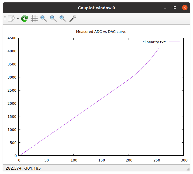
| > > | The ESP32 has two 12 bit SAR (Successive Approximation Register) Analogue to Digital Converters (ADCs) and two 8 bit Digital to Analogue Converters on chip. Checking for drivers in the MicroPython manual I only find a description of the ADCThe ADCADC 2 is used for WiFi and therefore not accessible to us. ADC 1 however has multiplexed input and 8 ADC channels are available for use (on Pins 32-39). The ADC has a range 0..1V but attenuators are available. If we set the attenuation to 11 DB we get a voltage range of approximately 0 .. 3.6 V. Pin 36 and pin 26 are available on the WeMos D1 bus but pins on the ESP32 CPU card can also be used (e.g. pin 33, 34, 35).The DACThe DACs are accessible on pins 25 and 26. Since there is no description in the manual, here is the way how to access the DAC: from machine import Pin,DACfrom time import sleep_ms dac = DAC(Pin(26)) print("Running a triangular wave form with a frequency of ~ 1 Hz on pin 26") while True: for i in range(256): dac.write(i) sleep_ms(2) for i in range(256): dac.write(256-i-1) sleep_ms(2) This will generate a slow triangular wave form that can be observed on a multi-meter. Checking linearityIf we connect the DAC output to the input of an ADC channel and we slowly ramp up the DAC value from 0 to its maximum and we read back the signal level with an ADC, then we expect a perfectly linear curve. This is true under the condition that both, the DAC and the ADC are perfectly linear.
| |||||||
-- Comments\ No newline at end of file | ||||||||
| Added: | ||||||||
| > > |
| |||||||
Revision 12020-07-26 - UliRaich
| Line: 1 to 1 | ||||||||
|---|---|---|---|---|---|---|---|---|
| Added: | ||||||||
| > > |
Exercise 9: Analogue to Digital (ADC) and Digital to Analogue (DAC) conversionArticle text. --Comments | |||||||
View topic | History: r10 < r9 < r8 < r7 | More topic actions...
Ideas, requests, problems regarding TWiki? Send feedback

