Analogue to Digital (ADC) and Digital to Analogue (DAC) conversion
Introduction
The ESP32 has two 12 bit SAR (Successive Approximation Register) Analogue to Digital Converters (ADCs) and two 8 bit Digital to Analogue Converters on chip. Checking for drivers in the MicroPython manual I only find a description of the ADCThe ADC
ADC 2 is used for WiFi and therefore not accessible to us. ADC 1 however has multiplexed input and 8 ADC channels are available for use (on Pins 32-39). The ADC has a range 0..1V but attenuators are available. If we set the attenuation to 11 DB we get a voltage range of approximately 0 .. 3.6 V. Pin 36 and pin 26 are available on the WeMos D1 bus but pins on the ESP32 CPU card can also be used (e.g. pin 33, 34, 35).The DAC
The DACs are accessible on pins 25 and 26. Since there is no description in the manual, here is the way how to access the DAC:from machine import Pin,DAC
from time import sleep_ms
dac = DAC(Pin(26))
print("Running a triangular wave form with a frequency of ~ 1 Hz on pin 26")
while True:
for i in range(256):
dac.write(i)
sleep_ms(2)
for i in range(256):
dac.write(256-i-1)
sleep_ms(2)
This will generate a slow triangular wave form that can be observed on a multi-meter.
Checking linearity
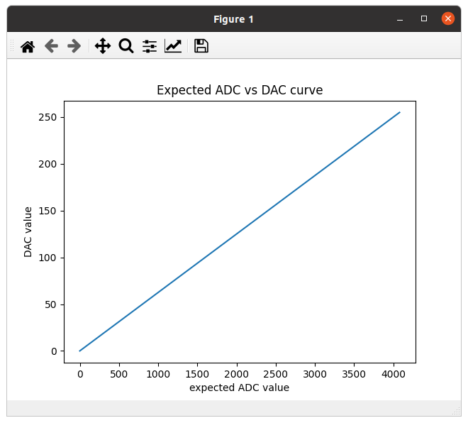
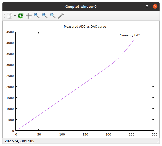
If we connect the DAC output to the input of an ADC channel and we slowly ramp up the DAC value from 0 to its maximum and we read back the signal level with the ADC, then we expect a perfectly linear curve. This is true under the condition that both, the DAC and the ADC are perfectly linear.| Linearity curve expected | Linearity curve measured |
|---|---|
 |
 |
Verifying linearity with an external ADS1115
The ADS1115 is a high precision 16 bit Sigma/Delta ADC with an I2C interface. It can easily be connected to the WeMos D1 bus as follows:| ADS 1115 | WeMos D1 bus and ESP32 | WeMos D1 bus and ESP8266 |
| Vdd | 3.3V | 3.3V |
| Gnd | Gnd | Gnd |
| SCL | D1: GPIO 22 | D1: GPIO 5 |
| SDA | D2: GPIO 21 | D2: GPIO 4 |
| A0 | DAC 2: GPIO 26 |
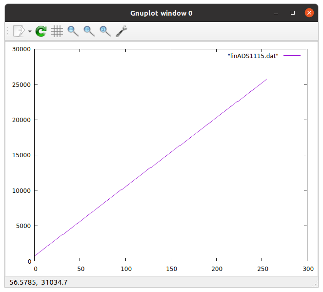 Note the change in scale on the y axis. The ADS1115 is a 16 bit ADC while the ESP32 has only 12 bits. The maximum value on the y axis depends on the input voltage range selected.
This clearly shows that the ESP32 ADC is the culprit!
Correcting the non-linearity
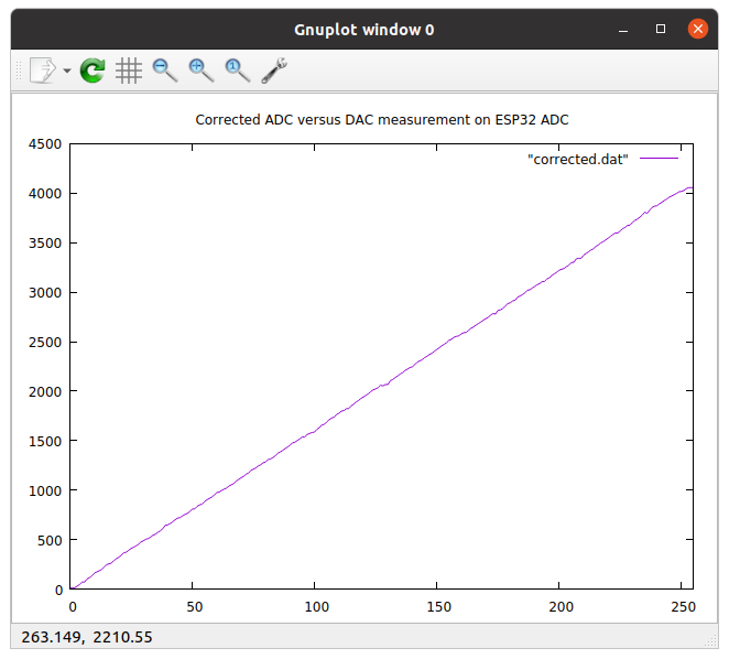
Now that we know that the DAC is nicely linear and it is the ADC introducing the non-linearity we can try to correct for it using our first DAC vs ADC measurement as calibration curve. If we can calculate the DAC value from the ADC output we can also calculate the corrected ADC value. For this to work we must invert (replace x by y and vice versa) the function adc = y = f(x) where x is the DAC value. This is the function of the first plot. Then we fit a polynomial to the inverted curve and finally we use this polynomial to correct the values read from the ADC. Here is a graph when fitting a polynomial of grade 5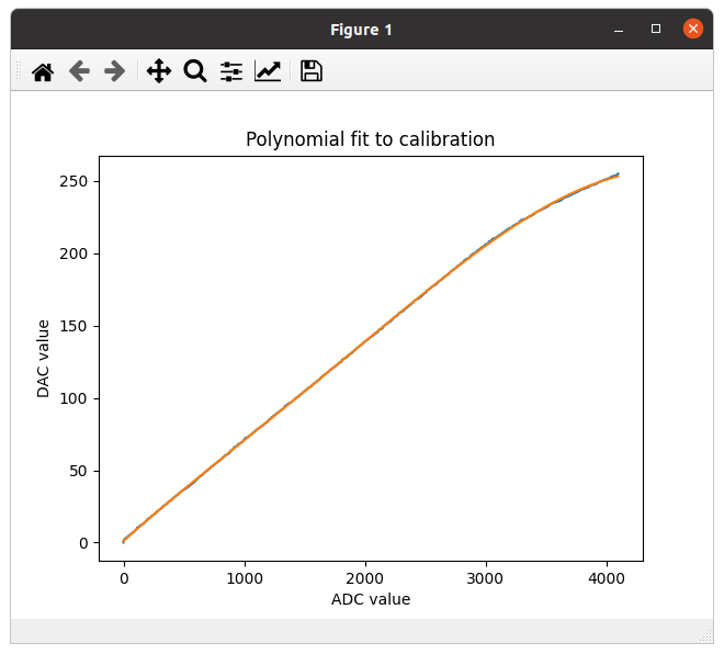 The fit returns the coefficients (a..e) of the polynomial and we can use this to correct for linearity. Instead of returning the raw ADC value we enter it into the polynomial and return the calculated value multiplied by 16 to get 0..4096 instead of 0..256.
Here is the DAC versus ADC measurement on the ESP32 ADC after correction:
A pulse generator on the DAC
In order to bring up the pulse generator on the DAC we will need an oscilloscope to observe the signals. In out toolbox we have a small number of Hantek6022 scopes for which driver software is available. I tried to bring up the scope staring from the source at https://github.com/OpenHantek/OpenHantek6022Making the Hantek6022 oscilloscope work
In order to build OpenHantek from source you will needed to install a few additional packages:- qttool5-dev for Qt5Linguist
- libusb-1.0.0-dev
- libfftw3-dev
mkdir build cd build cmake .. This will create the Makefile for you. All that is left is making the project. Finally you must allow user USB access to the Oscilloscope by copying 60-hantek.rules which you find in the utils/udev_rules directory to /etc/udev/rules.d. Unplug and re-plug your Hantek scope (Use the black USB connector). After compilation you will find the OpenHantek binary in build/openhantek.
 --
-- Comments
| I | Attachment | History | Action | Size | Date | Who | Comment |
|---|---|---|---|---|---|---|---|
| |
corrected.png | r1 | manage | 37.6 K | 2020-07-31 - 07:39 | UliRaich | |
| |
expected.png | r2 r1 | manage | 37.0 K | 2021-07-05 - 17:59 | UliRaich | |
| |
fit.png | r1 | manage | 31.7 K | 2020-07-31 - 07:27 | UliRaich | |
| |
linADS1115.png | r1 | manage | 30.2 K | 2020-07-30 - 13:30 | UliRaich | |
| |
linearity.png | r1 | manage | 34.4 K | 2020-08-07 - 14:41 | UliRaich | |
| |
openhantek.png | r1 | manage | 93.7 K | 2020-07-31 - 14:42 | UliRaich | |
| |
polynomial.png | r2 r1 | manage | 2.3 K | 2020-08-07 - 14:23 | UliRaich | |
| |
polynomialv2.png | r1 | manage | 2.3 K | 2020-08-07 - 14:25 | UliRaich | |
| |
restrictedLinearity.png | r1 | manage | 29.2 K | 2020-07-30 - 12:14 | UliRaich |
Ideas, requests, problems regarding TWiki? Send feedback


