| |
| META TOPICPARENT |
name="WebHome" |
The Hardware
The CPU card |
| | While the ESP32-wroom-32 uses GPIO 2 for its on-board user LED the ESP32-wrover-b uses GPIO 19.
The ESP32-wrover-b has a design flaw: GPIO 16 connected to pin D3 and GPIO 17 connected to pin D4 cannot be used to control sensors because these GPIO lines are used to control the PSRAM. This means that the CPU is incompatible with any shield using pins D3 and D4. Other GPIO lines should have been made available instead. |
|
>
> |
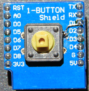
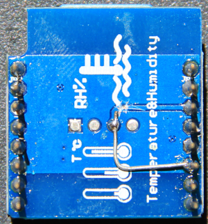
Checking the hardware table below shows that only the push button shield (D3) and the DHT11 (D4) use the forbidden pins. I therefore made hardware patches to connect their forbidden pins to D1.
| The patches pus button shield |
The patched DHT11 shield |
 |
 |
|
| | The Base Board
This board has no active elements but it connects sensor shields to the CPU board. Like this the necessary connections are made in a Lego based manner by just plugging modules together without any further cable connections or soldering. |
| |
|
|
<
< |
| 1 button shield |
D3 |
GPIO 0 |
GPIO 17 |
on / off push button |
|
>
> |
| 1 button shield |
D3
patched to D1 |
GPIO 0
patched to GPIO 5 |
GPIO 17
patched to GPIO 22 |
on / off push button |
|
| |
| WS2812B RGB shield |
D2 |
GPIO 4 |
GPIO 21 |
addressable rgb LED |
| WS2812B RGB ring |
D0 |
GPIO 16 |
GPIO 26 |
7 LED WS2812 ring |
DS1307 RTC and data logger |
D1
D2 D5
D6
D7
D8 |
GPIO 5 I2C SCL
GPIO 4 I2C SDA GPIO 14 SPI Clock
GPIO 12 SPI MOSI
GPIO 13 SPI MISO
GPIO 15 SPI CS |
GPIO 22 I2C SCL
GPIO 21 I2C SDA GPIO 18 SPI clock
GPIO 19 SPI MOSI
GPIO 23 SPI MISO
GPIO 5 SPI CS |
Real Time Clock SD card interface |
| Buzzer shield |
D5
D6
D7
D8 |
GPIO 14 (default)
GPIO 12
GPIO 13
GPIO15 |
GPIO 18 (default)
GPIO 19
GPIO 23
GPIO 5 |
passive buzzer |
| BMP180 shield |
D1
D2 |
GPIO 5 I2C SCL
GPIO 4 I2C SDA |
GPIO 22 I2C SCL
GPIO 21 I2C SDA |
I2C barometric pressure sensor and
temperature sensor |
|
|
<
< |
| DHT11 shield |
D4 |
GPIO 2 |
GPIO 16 |
temperature and humidity sensor |
|
>
> |
| DHT11 shield |
D4
patched to D1 |
GPIO 2
patched to GPIO 5 |
GPIO 16
patched to GPIO 22 |
temperature and humidity sensor |
|
| |
| OLED shield |
D1
D2 |
GPIO 5 I2C SCL
GPIO 4 I2C SDA |
GPIO 22 I2C SCL
GPIO 21 I2C SDA |
64x48 pixel display with SSD1036 I2C controller |
| TFT shield |
D0
D8 |
GPIO 16 CS
GPIO 15 DC |
GPIO 26 CS
GPIO 5 DC |
128x128 pixel display with ST7735 SPI controller |
| DS18B20 shield |
D2 |
GPIO 4 |
GPIO 21 |
1-wire digital temperature sensor |
|
| |
| META FILEATTACHMENT |
attachment="wrover.png" attr="" comment="" date="1594538242" name="wrover.png" path="wrover.png" size="256781" user="UliRaich" version="1" |
| META FILEATTACHMENT |
attachment="esp32V1.png" attr="" comment="" date="1594538935" name="esp32V1.png" path="esp32V1.png" size="246295" user="UliRaich" version="1" |
| META FILEATTACHMENT |
attachment="esp32-wrover-b_datasheet_en.pdf" attr="" comment="" date="1594539210" name="esp32-wrover-b_datasheet_en.pdf" path="esp32-wrover-b_datasheet_en.pdf" size="520362" user="UliRaich" version="1" |
|
|
>
> |
| META FILEATTACHMENT |
attachment="pushbuttonMod.png" attr="" comment="" date="1594579032" name="pushbuttonMod.png" path="pushbuttonMod.png" size="229955" user="UliRaich" version="1" |
| META FILEATTACHMENT |
attachment="dht11Mod.png" attr="" comment="" date="1594579032" name="dht11Mod.png" path="dht11Mod.png" size="235975" user="UliRaich" version="1" |
|


