The Hardware
The CPU card
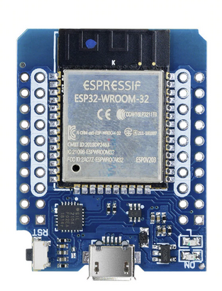
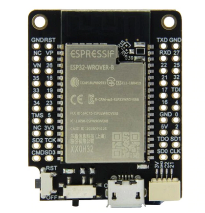
The ESP8266 CPU card has the following pinouts: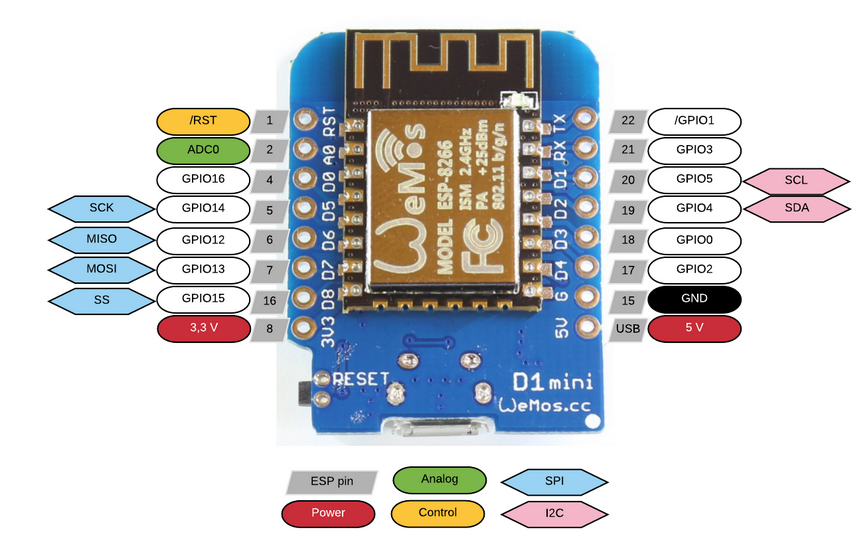 There are two different ESP32 CPU cards available for the WeMos D1 mini bus. The first card is based on an ESP-wroom-32 CPU while the second one uses the ESP-wrover-b chip.
Both cards have
 - 2 low-powerXtensa®32-bitLX6 microprocessors
- 520 KB of on-chip SRAM for data and instructions
- 4 MB of SPI flash
- I2C, I2S, SPI interface
- 3 UARTs, 12 bit ADC up to 18 channels, 8 bit DAC
| ESP-WROOM-32 | ESP-WROVER_B |
 |
 |
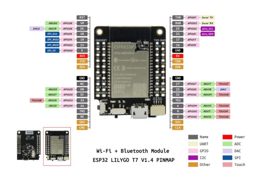 The circuit diagram of the LiyGo T7 V1.4 and 1.5 can be found at https://github.com/LilyGO/TTGO-T7-Demo
!!! Attention !!!
While the ESP32-wroom-32 uses GPIO 2 for its on-board user LED the ESP32-wrover-b uses GPIO 19. The ESP32-wrover-b has a design flaw: GPIO 16 connected to pin D3 and GPIO 17 connected to pin D4 cannot be used to control sensors because these GPIO lines are used to control the PSRAM. This means that the CPU is incompatible with any shield using pins D3 and D4. According to the LilyGo (provider of the CPU board) engineer GPIO 25 can be jumpered to D3 (GPIO 16) and GPIO 4 can be jumpered to D4 (GPIO 16). Doing this will allow to use the bus lines on the new GPIO connections. Checking the hardware table below shows that only the push button shield (D3) and the DHT11 (D4) use the forbidden pins. I therefore made hardware patches to connect their forbidden pins to D1. Having had the LilyGo information before I could have left the boards unchanged and added jumpers to the CPU board.| The patches pus button shield | The patched DHT11 shield |
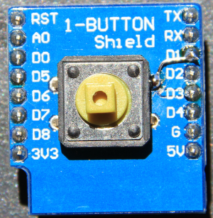 |
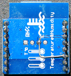 |
The Base Board
This board has no active elements, but it connects sensor shields to the CPU board. The connections are made in a Lego-based manner by just plugging modules together without any further cable connections or soldering.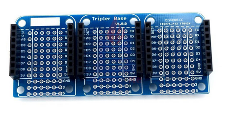
Switches
Two different types of switches are available as shields: a mechanical push button switch and a PIR sensor.| mechanical switch | PIR sensor |
 |
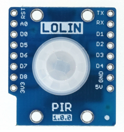 |
LEDs
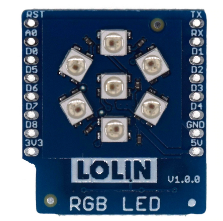
On the CPU card, there is a user programmable LED, used in the exercise on LEDs. This is a simple, single color (blue) LED.In the series of shields, we can also find an LED chain with 7 addressable WS2812 RGB LEDs.
Temperature and Humidity Sensors and Barometric Pressure Sensor
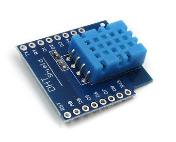
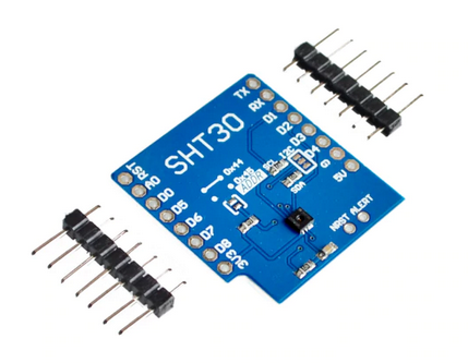
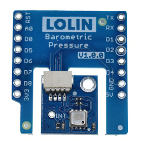
There are several environmental sensors of which we will use the DHT11 and the SHT30 temperature and humidity sensors. We work with both sensors in the exercises because these shields use quite different communication protocols, which we want to study. In addition to the temperature and humidity sensors, we have a barometric pressure sensor, (which also allows to measure ambient temperature) the BMP180. With these 3 sensors, we can construct a simple weather station.| DHT11 temperature and humidity sensor | SHT30 I2C temperature and humidity sensor | BMP180 barometric pressure sensor |
 |
 |
 |
Real Time Clock and Data Logging
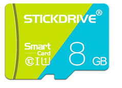
In order to store data taken with the environmental sensors, we us a micro SD card supplied with the Real-Time Clock and Data Logger card. With the Real-Time Clock we can get a time stamp, telling us when the data have been taken. 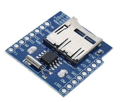 |
 |
Displays
Of course we can transfer the measurement data to a PC over the Internet and use the plotting facilities on the PC to graphically present the data but it may sometimes be interesting to show the data also on the micro-controller, without the need of Internet access. This is possible with TFT screens. The screeen we will use has a resolution of 128*128 pixels and text as well as simple pixel-graphics is possible with these devices.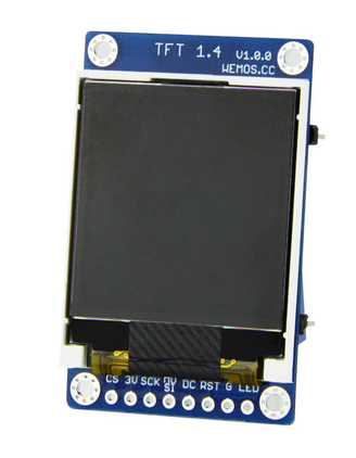
Motors
You can also control different types of motors with the ESP32. To demonstrate this, we use the motor controller shield. 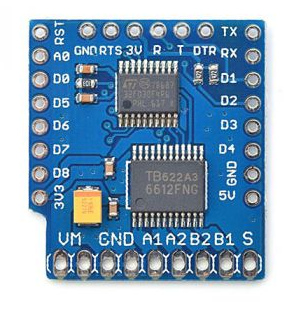 |
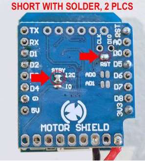 |
| Motor shield front view | Motor shield back view Please notice the 2 solder jumpers that must be made |
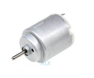
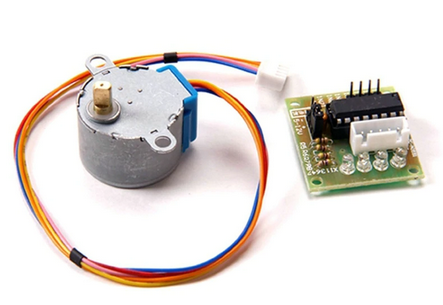
| DC motor | servo motor | stepping motor |
 |
 |
 |
| Module | Connections | GPIO on ESP8266 | GPIO on ESP32 | Functionality |
|---|---|---|---|---|
| WROVER CPU board | D3 D4 |
GPIO 17 GPIO 16 |
used by PSRAM on WROVER cannot be used by shields |
|
| Re-use pins D3 and D4 on WROVER CPU board: |
D3 D4 |
GPIO 27 connected to GPIO 17 GPIO 25 connected to GPIO 16 |
then use GPIO 25 and GPIO 27 | |
| 1 button shield | D3 patched to D1 |
GPIO 0 patched to GPIO 5 |
GPIO 17 patched to GPIO 22 |
on / off push button |
| WS2812B RGB shield | D2 | GPIO 4 | GPIO 21 | addressable rgb LED |
| WS2812B RGB ring | D0 | GPIO 16 | GPIO 26 | 7 LED WS2812 ring |
| SD card shield | D5 D6 D7 D8 |
GPIO 18 SPI clock GPIO 19 SPI MISO GPIO 23 SPI MOSI GPIO 15 CS |
||
| DS1307 RTC and data logger |
D1 D5 |
GPIO 5 I2C SCL GPIO 14 SPI Clock |
GPIO 22 I2C SCL GPIO 18 SPI clock |
Real Time Clock
SD card interface
|
| Buzzer shield | D5 D6 D7 D8 |
GPIO 14 (default) GPIO 12 GPIO 13 GPIO15 |
GPIO 18 (default) GPIO 19 GPIO 23 GPIO 5 |
passive buzzer |
| BMP180 shield | D1 D2 |
GPIO 5 I2C SCL GPIO 4 I2C SDA |
GPIO 22 I2C SCL GPIO 21 I2C SDA |
I2C barometric pressure sensor and temperature sensor |
| DHT11 shield | D4 patched to D1 |
GPIO 2 patched to GPIO 5 |
GPIO 16 patched to GPIO 22 |
temperature and humidity sensor |
| 64x48 pixel OLED shield | D1 D2 |
GPIO 5 I2C SCL GPIO 4 I2C SDA |
GPIO 22 I2C SCL GPIO 21 I2C SDA |
64x48 pixel display with SSD1036 I2C controller |
| 128x128 pixel TFT shield | D0 D8 |
GPIO 16 CS GPIO 15 DC |
GPIO 26 CS GPIO 5 DC |
128x128 pixel display with ST7735 SPI controller |
| 320 x 240 pixel TFT screen and touch screen | D8 D7 D6 D5 D0 D3 |
GPIO 5 (TFT_DC) GPIO 23 (MOSI) GPIO 19 (MISO) GPIO 18 (SCK) GPIO 26 (TFT_CS) GPIO 25 (TS_CS) |
320x240 pixel display with ili9341 controller and xpt2046 touch screen controller GPIO 25 must be jumpered to GPIO 17 on the WROVER board |
|
| DS18B20 shield | D2 | GPIO 4 | GPIO 21 | 1-wire digital temperature sensor |
| SHT30 shield | D1 D2 |
GPIO 5 I2C SCL GPIO 4 I2C SDA |
GPIO 22 I2C SCL GPIO 21 I2C SDA |
I2C temperature and humidity sensor |
| Motor shield | D1 D2 |
GPIO 5 I2C SCL GPIO 4 I2C SDA |
GPIO 22 I2C SCL GPIO 21 I2C SDA |
Controlling DC Motors |
| Servo Motor | D0 | GPIO 16 | GPIO 26 | Signal pin of SG90 servo motor |
| LED Matrix shield | D5 GPIO 14 CLK D7 GPIO 13 Din |
GPIO 14: CLK GPIO 13: Din |
GPIO 18: CLK GPIO 23: Din |
8x8 LED Matrix |
| PIR sensor | D1 (default) | GPIO 5 | GPIO 22 | Passive Infrared Switch |
| BH1750 sensor | D1 D2 |
GPIO 5 I2C SCL GPIO 4 I2C SDA |
GPIO 22 I2C SCL GPIO 21 I2C SDA |
Ambient light sensor |
| Relay | D0 | GPIO 16 | GPIO 26 | Relay shield |
| IR receiver IR transmitter |
D2 D1 |
GPIO 21 GPIO 22 |
| Dx | GPIO ESP8266 | GPIO ESP32 WROOM | GPIO ESP32 WROVER |
|---|---|---|---|
| A0 | ADC 0 | 36 | 36 |
| D0 | 16 | 26 | 26 |
| D1 I2C SCL | 5 | 22 | 22 |
| D2 I2C SDA | 4 | 21 | 21 |
| D3 | 0 | 17 | patched to 27 |
| D4 | 18 | 16 | patched to 25 |
| D5 SPI clock | 14 | 18 | 18 |
| D6 SPI MISO | 12 | 19 | 19 |
| D7 SPI MOSI | 13 | 23 | 23 |
| D8 SPI CS | 15 | 5 | 5 |
Comments
| I | Attachment | History | Action | Size | Date | Who | Comment |
|---|---|---|---|---|---|---|---|
| |
bmp180.png | r2 r1 | manage | 132.7 K | 2020-05-14 - 18:10 | UliRaich | |
| |
button.png | r1 | manage | 279.6 K | 2020-05-14 - 17:57 | UliRaich | |
| |
dcMotor.png | r1 | manage | 52.1 K | 2020-05-14 - 18:13 | UliRaich | |
| |
dht11Mod.png | r1 | manage | 230.4 K | 2020-07-12 - 18:37 | UliRaich | |
| |
equip.odt | r1 | manage | 7231.2 K | 2021-06-07 - 08:12 | UliRaich | |
| |
esp32-wroom-32_datasheet_en.pdf | r1 | manage | 512.3 K | 2020-05-14 - 17:35 | UliRaich | |
| |
esp32-wrover-b_datasheet_en.pdf | r1 | manage | 508.2 K | 2020-07-12 - 07:33 | UliRaich | |
| |
esp32.png | r2 r1 | manage | 240.5 K | 2020-07-12 - 07:17 | UliRaich | |
| |
esp32V1.png | r1 | manage | 240.5 K | 2020-07-12 - 07:28 | UliRaich | |
| |
esp8266.png | r1 | manage | 390.8 K | 2022-08-24 - 17:17 | UliRaich | |
| |
leds.png | r1 | manage | 292.6 K | 2020-05-14 - 18:00 | UliRaich | |
| |
motorController.png | r1 | manage | 303.5 K | 2020-05-14 - 18:13 | UliRaich | |
| |
motorShieldBack.png | r1 | manage | 192.2 K | 2020-06-24 - 15:25 | UliRaich | |
| |
motorShieldFront.png | r1 | manage | 170.7 K | 2020-06-24 - 15:25 | UliRaich | |
| |
pir.png | r1 | manage | 319.4 K | 2020-05-14 - 17:57 | UliRaich | |
| |
pushbuttonMod.png | r1 | manage | 224.6 K | 2020-07-12 - 18:37 | UliRaich | |
| |
rtc.png | r1 | manage | 172.2 K | 2020-05-14 - 18:24 | UliRaich | |
| |
sd_card.png | r1 | manage | 38.7 K | 2020-05-25 - 18:23 | UliRaich | |
| |
servo.png | r1 | manage | 143.0 K | 2020-05-14 - 18:13 | UliRaich | |
| |
sht30.png | r1 | manage | 123.1 K | 2020-05-14 - 18:06 | UliRaich | |
| |
stepper.png | r1 | manage | 134.6 K | 2020-05-14 - 18:13 | UliRaich | |
| |
tftScreen.png | r1 | manage | 144.4 K | 2020-05-14 - 18:31 | UliRaich | |
| |
tripleBase.png | r1 | manage | 196.1 K | 2020-05-14 - 17:41 | UliRaich | |
| |
trippleBase.png | r1 | manage | 153.3 K | 2020-05-14 - 17:38 | UliRaich | |
| |
wemosDHT11.png | r1 | manage | 113.4 K | 2020-05-14 - 18:07 | UliRaich | |
| |
wrover.png | r1 | manage | 250.8 K | 2020-07-12 - 07:17 | UliRaich | |
| |
wroverbPinout.jpg | r1 | manage | 52.3 K | 2020-07-28 - 15:19 | UliRaich |
Ideas, requests, problems regarding TWiki? Send feedback


