Hardware access, the General Purpose Input Output (GPIO) pins.
Running the programs on the PC
Up to now, all programs we have written can be executed on the ESP32 but also on the PC. Make sure you import
time and not
utime and do not use
sleep_ms, but use
sleep instead. So... instead of sleep_ms(100) use sleep(0.1) and you will be able to run the programs on your PC with
python3 name_of_your_program.py
Please give it a try.
Accessing the hardware
The connection of digital input or output signals is made through
General
Purpose
Input
Output pins. These pins can be programmed to output (control) a signal level or to input (acquire) a signal level.
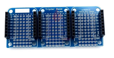
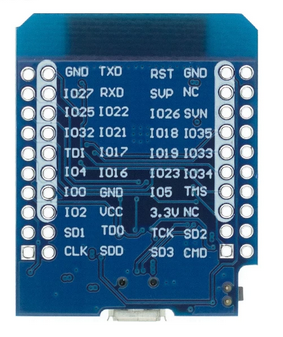
The base board and the back of the CPU card look like this (the pins on the ESP32 CPU are mirrored with respect to the base board):
As you can see, the pins on the triple board are marked, as are the ones on the ESP32 COU board. Please note that the pins on the CPU card are mirrored.
In the table above, the IO numbers correspond to the GPIO numbers. As you can see, there are 10 such GPIO lines at your disposal. Most of these lines can be reallocated to different functions. They can be used as serial line (3 serial ports) as I2C ports (2 hardware interfaces) or as SPI ports or mapped to Analogue to Digital (ADC) or Digital to Analog Converters (DAC). During the course, we will see how to reprogram GPIO 36 (SVP) to use the ADC. The CPU has a user programmable LED connected to GPIO 2.
Accessing the user programmable LED
In order to understand how to access GPIO line we must look up the MicroPython documentation. Select
Quick reference for the ESP32 and search for
Pins and GPIO 
.
The schematic diagram of the LED connection looks like this:

When the output level on GPIO 2 is zero, then there is no voltage across the LED and the resistor. The LED is switched off. If GPIO 2 is at high level, then there is a voltage of 3.3V across the LED and the resistor and the LED lights up. The 330 Ω resistor limits the current flowing through the LED to 10 mA.
As you can see, MicroPython supplies a Python module named
Pin, which is used to program GPIO pins. In order to control a LED the corresponding pin must be programmed to be an output line.
from machine import Pin
from time import sleep
led = Pin(2,Pin.OUT) # the led is connected to GPIO 2 and this is an output line
led.on()             # switches the LED on
sleep(2)             # keeps it on for 2 s
led.off()            # and switches it off again.
Instead of the on() and off() functions, you may also use
led.value(1)         # switches the LED on
led.value(0)         # switches it off
Reading a switch
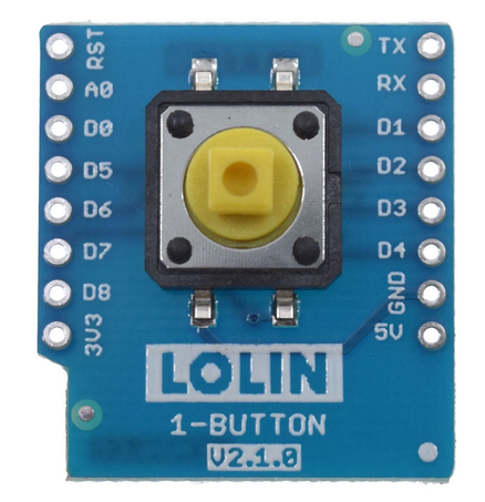
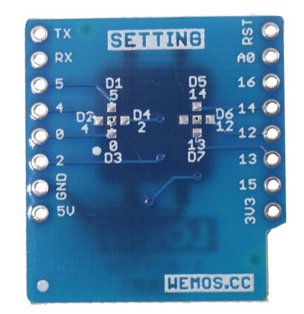
While for the previous exercises as well as for programming the user LED we only needed the CPU card, the push button is located on a second card (sometimes also called shield). If you look at the backside of the card very, very attentively, you may see that there is a bridge from the D3 pad (GPIO 17) to the middle pad. This means that the push button is connected to GPIO 17 by default. Cutting this bridge and creating a solder bridge from D1 .. D7 to a middle pad allows reconfiguring the push button and use it on a different GPIO line
The circuit diagram for s push button switch connection to the ESP32 GPIO line should look like this:

You can see, however, that there is no (pull-up) resistor on the pushbutton card. In fact, we can connect such a pull-up resistor by program on the ESP32 GPIO line.
Here is a script that reads the state of the pushbutton switch every 100 ms and prints the result:
from machine import Pin
from time import sleep_ms

pb = Pin(17, Pin.IN, Pin.Pin.PULL_UP)   # set the GPIO line 0 to input and add a pull-up resistor
while True:
     if pb.value() :                    # if we read a high state, the switch is not pressed
           print("Push button is released")
     else:
           print("Push button is pressed")
     sleep_ms(100)
I think we are ready for another exercise session
ExerciseSheets#ThirdSession
In the next step, we will read analogue signal levels:
Analogue Signals
--
 Uli Raich - 2022-10-15
Comments


 When the output level on GPIO 2 is zero, then there is no voltage across the LED and the resistor. The LED is switched off. If GPIO 2 is at high level, then there is a voltage of 3.3V across the LED and the resistor and the LED lights up. The 330 Ω resistor limits the current flowing through the LED to 10 mA.
As you can see, MicroPython supplies a Python module named Pin, which is used to program GPIO pins. In order to control a LED the corresponding pin must be programmed to be an output line.


 You can see, however, that there is no (pull-up) resistor on the pushbutton card. In fact, we can connect such a pull-up resistor by program on the ESP32 GPIO line.
Here is a script that reads the state of the pushbutton switch every 100 ms and prints the result:


