The WeMos D1 mini and its sensor and actuator shields
Introduction
We have seen that the ESP01 can be programmed with micro Python and that there are add-on sensor boards available. However, when we connect the sensor board we lose the serial connection to the PC. This can be corrected by soldering extra connectors to the top of the ESP01 board but this is fiddly and needs good soldering equipment and good soldering skills. The other option is to get access to the ESP01 through WiFi using WebRepl A better and only slightly more expensive solution (we are talking about ~ 3.5 US$ instead of 2.5 US$) is the Wemos D1 mini board. This board gives us more I/O connections and many more sensor and actuator shields are readily available on the market.The processor board
ESP8266
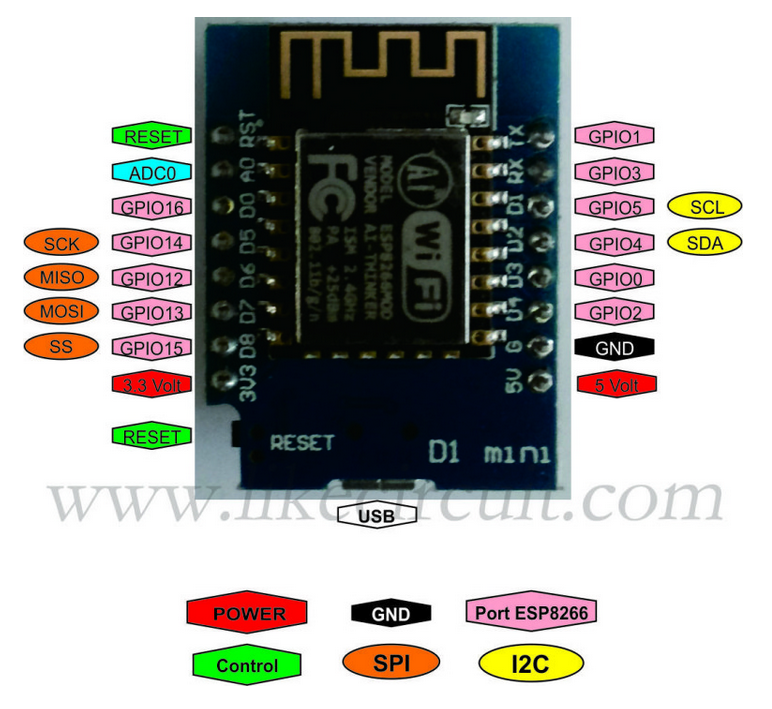
The processor board uses an Espressif ESP8266 processor chip and provides 4 MBytes of flash memory. You will find a description of the pinout at https://www.teachmemicro.com/getting-started-wemos-d1-mini
 In contrast to a PC the WeMos D1 mini has only very limited memory resources. While 4 MBytes of flash memory is rather comfortable, the amount of RAM (80 K) is a very limiting factor. When running micropython a mere 30 kBytes is left for your Python programs. There are essentially 2 ways to make most out of the small amount of RAM:
 - You can pre-compile your programs to byte code, which takes less space in RAM
- You can code freeze driver libraries, which means you integrate their byte code into The micropython image. This however means, that you must compile your own version of micropython and flash it into the WeMos D1 CPU.
ESP32
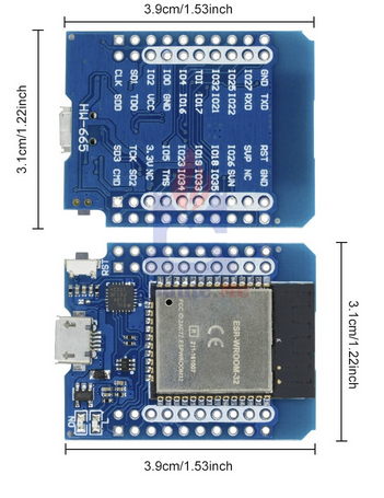
As an alternative you have a CPU board based on the more powerful ESP32: As for the ESP8266 there is a micropython port for the ESP32. The drivers are essentially the same, the pinout of the board however (GPIO numbers for the pins) is different. This means that for every driver we must only change the GPIO number. Since it is possible to find out from micropython on which platform we run (sys.platform tells you if your CPU is an "esp8266" or an "esp32") we can check for the CPU type and adapt the pin numbering as a consequence.
Here is a comparison of the pin assignments for the 2 CPUs:
ESP8266
| RESET | RST | Tx | GPIO 1 | ||
| ADC0 | A0 | Rx | GPIO 3 | ||
| GPIO 16 | D0 | D1 | GPIO 5 | SCL | |
| SCK | GPIO 14 | D5 | D2 | GPIO 4 | SDA |
| MOSI | GPIO 12 | D6 | D3 | GPIO 0 | |
| MISO | GPIO 13 | D7 | D4 | GPIO 2 | |
| SS | GPIO 15 | D8 | GND | GND | |
| 3.3V | 3V3 | 5V | 5V |
| RESET | RST | Tx | |||
| ADC1 channel 0 | GPIO 36 | SVP | Rx | ||
| GPIO 26 | IO26 | IO22 | GPIO 22 | SCL | |
| SCK | GPIO 18 | IO18 | IO21 | GPIO 21 | SDA |
| MOSI | GPIO 19 | IO19 | IO17 | GPIO 17 | |
| MISO | GPIO 23 | IO23 | IO16 | GPIO 16 | |
| SS | GPIO 5 | IO5 | GND | GND | |
| 3.3V | 3V3 | 5V | 5V |
Sensor Shields
A big number of sensor and actuator boards are available. You will find a complete list with their description at https://docs.wemos.cc/en/latest/d1_mini_shiled/- The triple base and prototype boards
- A simple Pushbutton Switch
- The WS2812B rgb LED
- The DS1307 real time clock and data logger
- The buzzer shield
- The bmp180 shield featuring an atmospheric pressure and a temperature sensor
- The Oled shield
- The DS18B20 shield with a Dallas DS18B20
 1-wire digital temperature sensor
- The LED matrix shield
- The SHT-30 shield with a SHT-30 I2C digital temperature and humidity sensor
- The DHT11 shield with a DHT11 digital temperature and humidity sensor. This device uses its own private serial communication protocol
| Module | Connections | GPIO on ESP8266 | GPIO on ESP32 | Functionality |
|---|---|---|---|---|
| 1 button shield | D3 | GPIO 0 | GPIO 17 | on / off push button |
| WS2812B RGB shield | D2 | GPIO 4 | GPIO 21 | addressable rgb LED |
| WS2812B RGB ring | D0 | GPIO 16 | GPIO 26 | 7 LED WS2812 ring |
| DS1307 RTC and data logger |
D1 D5 |
GPIO 5 I2C SCL GPIO 14 SPI Clock |
GPIO 22 I2C SCL GPIO 18 SPI clock |
Real Time Clock
SD card interface
|
| Buzzer shield | D5 D6 D7 D8 |
GPIO 14 (default) GPIO 12 GPIO 13 GPIO15 |
GPIO 18 (default) GPIO 19 GPIO 23 GPIO 5 |
passive buzzer |
| BMP180 shield | D1 D2 |
GPIO 5 I2C SCL GPIO 4 I2C SDA |
GPIO 22 I2C SCL GPIO 21 I2C SDA |
I2C barometric pressure sensor and temperature sensor |
| DHT11 shield | D4 | GPIO 2 | GPIO 16 | temperature and humidity sensor |
| OLED shield | D1 D2 |
GPIO 5 I2C SCL GPIO 4 I2C SDA |
GPIO 22 I2C SCL GPIO 21 I2C SDA |
64x48 pixel display with SSD1036 I2C controller |
| DS18B20 shield | D2 | GPIO 4 | GPIO 21 | 1-wire digital temperature sensor |
| SHT30 shield | D1 D2 |
GPIO 5 I2C SCL GPIO 4 I2C SDA |
GPIO 22 I2C SCL GPIO 21 I2C SDA |
I2C temperature and humidity sensor |
| LED Matrix shield | D5 GPIO 14 CLK D7 GPIO 13 Din |
GPIO 14: CLK GPIO 13: Din |
GPIO 18: CLK GPIO 23: Din |
8x8 LED Matrix |
| PIR sensor | D4 (default) | GPIO 2 | GPIO 16 | Passive Infrared Switch |
| BH1750 sensor | D1 D2 |
GPIO 5 I2C SCL GPIO 4 I2C SDA |
GPIO 22 I2C SCL GPIO 21 I2C SDA |
Ambient light sensor |
| Relay | ||||
| IR receiver/transmitter |
- a driver directory containing programs testing the module without Cayenne communication
- a cayenne directory for the final program
Comments
| I | Attachment | History | Action | Size | Date | Who | Comment |
|---|---|---|---|---|---|---|---|
| |
d1MiniPinout.png | r1 | manage | 542.9 K | 2019-03-20 - 09:27 | UliRaich | |
| |
wemosEsp32.png | r1 | manage | 213.3 K | 2019-05-07 - 17:49 | UliRaich | |
| |
wemosd1mini.png | r1 | manage | 313.5 K | 2019-03-20 - 09:20 | UliRaich |
Topic revision: r13 - 2020-05-23 - TWikiAdminUser
Ideas, requests, problems regarding TWiki? Send feedback


