Analogue to Digital Conversion (ADC)
Goal:
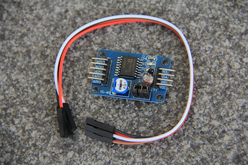
Apart from the digital to analogue converter where we created analog signal levels from digital values, we have only handled binary data, high or low. Many sensors however deliver analogue signals and we must first convert them into digital values before we can read the out and treat the data. The pcf8591 is an analogue to digital converter (ADC) which does exactly this. It is not a very good one, having only 8 bit resolution (how much is this in %?) and we have a much more precise, 16 bit ADC in our sensor kit, but the board on which the pcf8591 is mounted has already sensor delivering analogue signals is it is therefore very convenient to make our first experience with A to D conversion with such a board. In particular the board has a potentiometer mounted on it with which we can easily create different analogue signal levels and we can see immediately if our program see the changes. The pot is the blue and white device with the slit in its middle, next to it you have photo resistor and finally a thermistor, devices that change their resistivity with the light intensity or temperature respectively.
Exercise 1
Find out on which I2C address you can talk to the pcf8591. Write code to initialize the I2C bus using the pigpio library. Write the code needed to read all four channels. Check what happens when you change the potentiometer value. Does the digital value change? Check the same thing on the photo resistor and the thermistor.Exercise 2
Combine this exercise with the one on the LCD display and create a simple voltmeter. You can try to set a Voltage with the DAC and read it back with the ADC and display the result on the display. --Comments
| I | Attachment | History | Action | Size | Date | Who | Comment |
|---|---|---|---|---|---|---|---|
| |
adc.pdf | r1 | manage | 1556.4 K | 2017-11-27 - 10:37 | UnknownUser | |
| |
pcf8591ADC.odt | r1 | manage | 1120.5 K | 2017-10-25 - 18:48 | UnknownUser | |
| |
pcf8591front.png | r1 | manage | 1096.3 K | 2017-10-25 - 18:39 | UnknownUser |
Ideas, requests, problems regarding TWiki? Send feedback


