Implementing the Arduino toolbox
The program structure
As you would probably expect, the program will consist of three parts- a server running on the Arduino taking commands from Xcos and accessing the GPIO hardware
- an Xcos client implementing the Xcos blocks
- a protocol defining the communication between client and server
The communication protocol
The communication protocol must be as simple and short as possible in order to increase the speed and therefore the maximum possible sampling rate.The server itself is an Arduino sketch consisting essentially of a big switch statement. The first specifies the type of action to be taken or the device to talk to. For the moment only 2 devices are implemented:- version: returns the version number of the protocol server on the Arduino
- digital read or write
This allows to read the state of a GPIO line defined in the xcos block or to write a high or low state to this GPIO line. Before the xcos simuation (the scilab program on the PC) is started (pre-simulation) the mode of the GPIO line is set. - stepping motor
Here we set the GPIO pins associated to the stepping motor pulse to output in the pre-simulation step. The a "do one step" command is sent to the server.
Getting the server version
V: gets the server version code. The server answers with Vab where a is the major and b the minor version number e.g. V13 for version 1.3Reading or writing a digital GPIO line
Dan0 or Dan1: attaches GPIO line n. The last character defines if the line is input (0) or output (1). n is the GPIO pin number which can be '1' (0x31) up to '9' (0x39). For higher pin numbers just take the next ASCII characters. Having a look at the ASCII table tells us the pin number 10 will correspond to the ASCII characters with code (0x3A) which is ':', 11 corresponds to ';' and so on.Drn: Read the state of GPIO line n
Dwn0 or Dwn1 sets the GPIO line n to 0 or 1 respectively.

Controlling a stepper motor
In case of the stepper motor we need a means to define which GPIO pin is connected to which stepper motor coil. This is done with a command: Sanp: Where "S" identifies for the stepper motor device, "a" stands for "attach" n is the GPIO pin and p is the pulse (N1 .. N4 or the stepping motor driver module) . The command also programs the GPIO pins as output. Sa21 will therefore attach GPIO pin 2 to the first stepping motor driver input (N1 on the driver card). Sm: moves the stepping motor by 1 stepThe Arduino server program and the test procedure
With this information it is possible to develop the first version of the Arduino server. Since all it needs is input from the serial line we can write a simple C program to test the server. A program asking for the server version (and printing it) as well as the Arduino server are attached to this TWiki page. The Arduino server uses debugging code which prints each character received as well as the interpretation in makes out of it to a Softserial port with Rx connected to GPIO pin 11 and Tx connected to pin 10. This Softserial port can be attached to a USB to serial adapter and the output observed with a serial emulator program like minicom. The communication between Scilab and the Arduino happens on /dev/ttyUSB0, the debugging port should therefore be connected to /dev/ttyUSB1 (minicom -D /dev/ttyUSB1). Both, the test programs as well as the xcos toolbox, pass through the same serial library with the following calls: Since the test programs and the xcos toolbox use the same communication code we can be sure that once the server is tested with the test programs it will also work on the toolbox.
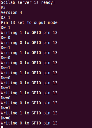
Here is a screen dump of the server output when we first read the server version and then blink the builtin LED (on GPIO pin 13) 5 times:
Since the test programs and the xcos toolbox use the same communication code we can be sure that once the server is tested with the test programs it will also work on the toolbox.
Here is a screen dump of the server output when we first read the server version and then blink the builtin LED (on GPIO pin 13) 5 times:
 And this is the output from the Arduino server onto /dev/ttyUSB1 when running the stepper motor test:
 And in fact you see the motor turn when it receives the Sm commands.
--
And in fact you see the motor turn when it receives the Sm commands.
-- Comments


| I | Attachment | History | Action | Size | Date | Who | Comment |
|---|---|---|---|---|---|---|---|
| |
ascii.png | r1 | manage | 70.1 K | 2019-01-07 - 16:49 | UliRaich | |
| |
blink.png | r1 | manage | 38.5 K | 2019-01-07 - 16:49 | UliRaich | |
| |
blink2.png | r1 | manage | 61.8 K | 2019-01-15 - 14:40 | UliRaich | |
| |
serialLib.png | r1 | manage | 22.5 K | 2019-01-15 - 14:28 | UliRaich | |
| |
stepper.png | r1 | manage | 15.1 K | 2019-01-15 - 14:28 | UliRaich |

|
|
|
|
Ideas, requests, problems regarding TWiki? Send feedback