

The 2 Line LCD Display and its HD44780 Controller


COPYRIGHT © 2024 by the contributing authors
Slide 1 of 36
Why a simple 2 line display?
Often embedded systems do not have a screen, keyboard and mouse associated with them.
Small devices in the field may nevertheless need to display some values to the user
Small and cheap LCD displays can take over this task
Our display can be used for many purposes (see the open day):
- Name display
- Weather station
- Voltmeter
COPYRIGHT © 2024 by the contributing authors
Slide 2 of 36
Our Display

COPYRIGHT © 2024 by the contributing authors
Slide 3 of 36
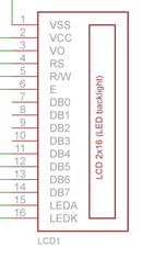
Interfacing the display

COPYRIGHT © 2024 by the contributing authors
Slide 4 of 36
The PCF8574 I2C interface
The PCF8574 I2C I/O expander allows to limit the number of connection wires to just four.
It is a kind of a shift register: serial in, parallel out
It is a kind of a shift register: serial in, parallel out
COPYRIGHT © 2024 by the contributing authors
Slide 5 of 36
How to program the display
We need to know:
How to program the PCF8574
Understand the HD44780 display controller
Understand the interface between the two
Since the display can be used for many different purposes,
writing a library is the thing to do!
COPYRIGHT © 2024 by the contributing authors
Slide 6 of 36
Interfacing signals
| The display needs a large number of interface signals to be able to work:
|
 |
COPYRIGHT © 2024 by the contributing authors
Slide 7 of 36
A data byte to be sent
 We will therefore need a great deal of bit fiddling
to create this data byte and to modify it to
We will therefore need a great deal of bit fiddling
to create this data byte and to modify it to - Set the back light on or off
- To send a pulse on the E (strobe) line
- bitwise or operator: |
- bitwise and operator: &
- bit inversion: ~
COPYRIGHT © 2024 by the contributing authors
Slide 8 of 36
The I/O expander
As you can see from the block diagram, the central part of the device
is a shift register. It can actually do both:

- serial to parallel conversion (write)
- and parallel to serial conversion (read)
COPYRIGHT © 2024 by the contributing authors
Slide 9 of 36
From the data sheet
 This means that when reading, we will read back
what has been written before, if the signals are pure output signals.
This means that when reading, we will read back
what has been written before, if the signals are pure output signals.Since the device will put all pins high with a low pull-up current, external signals can easily pull the pins low and thus you can read the state of these signals
COPYRIGHT © 2024 by the contributing authors
Slide 10 of 36
Writing the to HD4780 controller via the PCF8574

COPYRIGHT © 2024 by the contributing authors
Slide 11 of 36
Writing to PCF8574 via pigpio
Even though it looks complicated at first sight,
writing a data byte to the hd44780 controller via the
pcf8574 I/O extender is actually pretty simple:
 After this instruction the 8 data bits of bVal lie at the input of the hd44780 controller.
After this instruction the 8 data bits of bVal lie at the input of the hd44780 controller.
COPYRIGHT © 2024 by the contributing authors
Slide 12 of 36
The HD44780
The controller must generate the signals needed to driver the
LCD display and it must provide instructions to
- Reset the display
- Clear it
- Have cursor functions
- Enable/disable the cursor
- Move it, Home it ..
- Make it blink.
- Have character generators in ROM or
provide RAM memory to download character matrices (or both) - Allow to send characters and convert the ASCII code to
dot matrices understood by the display
- Switch from one line to the next
COPYRIGHT © 2024 by the contributing authors
Slide 13 of 36
HD44780 block diagram

COPYRIGHT © 2024 by the contributing authors
Slide 14 of 36
The HD44780 library
As already explained several times, a library must supply:
- The binary code: libhd44780.so
- The include file hd44780.h
COPYRIGHT © 2024 by the contributing authors
Slide 15 of 36
The function prototypes

COPYRIGHT © 2024 by the contributing authors
Slide 16 of 36
Using the library
In addition to the prototypes, have a look at the doxygen  documentation
and you should be able to program the display.
Of course you have to include
-I/opt/ucc/include in your CFLAGS
-L/opt/ucc/lib in your LDFLAGS
and -lhd4780 in your LDLIBS
However, we want to understand what is happening behind the scene!
documentation
and you should be able to program the display.
Of course you have to include
-I/opt/ucc/include in your CFLAGS
-L/opt/ucc/lib in your LDFLAGS
and -lhd4780 in your LDLIBS
However, we want to understand what is happening behind the scene!
COPYRIGHT © 2024 by the contributing authors
Slide 17 of 36
Testing access
Before starting to write the library we must first test if
- We can initialize the device ?
- We can write something to it and read it back ?
- Or can we find any other function showing us that the device responds?
COPYRIGHT © 2024 by the contributing authors
Slide 18 of 36
Back light
To give us some confidence, lets try to switch the back light on and off:
This one is easy as it does not access the hd44780. It does test the PCF8574 though! Switching bit 7 in the data word does the trick. Later we will read a byte from the display and and/or bit seven into the byte read before writing it back.
This one is easy as it does not access the hd44780. It does test the PCF8574 though! Switching bit 7 in the data word does the trick. Later we will read a byte from the display and and/or bit seven into the byte read before writing it back.
COPYRIGHT © 2024 by the contributing authors
Slide 19 of 36
HD44780 registers
The HD44780 has a single register select pin (RS)
indicating that there must be writable 2 registers:
- IR: the instruction register
- DR: the data register
COPYRIGHT © 2024 by the contributing authors
Slide 20 of 36
The DDRAM
The Display Data RAM stores data in 8 bit character codes.
It has a size of 80 characters which in our case corresponds
to 2 lines of 40 chars (of which only 2*16 will be used.

COPYRIGHT © 2024 by the contributing authors
Slide 21 of 36
2*16 character display

COPYRIGHT © 2024 by the contributing authors
Slide 22 of 36
Converting the 8bit code to a dot matrix
The hd44780 contains a character ROM which will convert the
8 bit character code (mainly ascii code) to
- a 5*8 dot matrix with 208 predefined characters
(this is what we will use) - a 5*10 dot matrix with 32 characters
COPYRIGHT © 2024 by the contributing authors
Slide 23 of 36
Character Generator

COPYRIGHT © 2024 by the contributing authors
Slide 24 of 36
Dot matrix and the display

COPYRIGHT © 2024 by the contributing authors
Slide 25 of 36
Interfacing to the MPU
The HD44780 can be controlled with 8 or with 4 data bits.
In 4 bit mode (this is what we use) with the higher 4 MPU bits connected to d4-d7. The hd44780 data lines d0 d3 are disabled
The lower four bits are used to drive
In 4 bit mode (this is what we use) with the higher 4 MPU bits connected to d4-d7. The hd44780 data lines d0 d3 are disabled
The lower four bits are used to drive
- RS (register select)
- RW (read / write)
- Strobe (E=enable)
- and back light
COPYRIGHT © 2024 by the contributing authors
Slide 26 of 36
Instruction Summary

COPYRIGHT © 2024 by the contributing authors
Slide 27 of 36
Instruction Summary (2)

COPYRIGHT © 2024 by the contributing authors
Slide 28 of 36
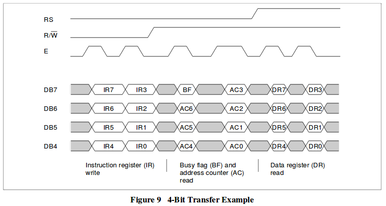
Writing to the HD44780 in 4-bit mode
In order to write to the IR or DR of the HD44780 in 4-bit mode we must:
- Prepare an 8 bit value and put the highest significant
- 4 bits of the data to be written into its lower 4 bits
- Set the R/W bit to low
- Setup the RS bit (0 for IR, 1 for DR)
- Strobe the data into the controller
- Repeat the same thing for the lower significant
8 bits of the data we want to write - Keep the BL bit constant
COPYRIGHT © 2024 by the contributing authors
Slide 29 of 36
Strobe function

COPYRIGHT © 2024 by the contributing authors
Slide 30 of 36
Writing a command and writing data
In my library I define 2 functions:
- hd44780WriteCmd (unsigned char cmd)
- hd44780PutC (char c)
COPYRIGHT © 2024 by the contributing authors
Slide 31 of 36
hd44780WriteCmd

COPYRIGHT © 2024 by the contributing authors
Slide 32 of 36
Timing diagrams 4 bit mode

COPYRIGHT © 2024 by the contributing authors
Slide 33 of 36
The initialization procedure

COPYRIGHT © 2024 by the contributing authors
Slide 34 of 36
Initialization Procedure (2)

COPYRIGHT © 2024 by the contributing authors
Slide 35 of 36
Initialization procedure (code)
These are the instructions:
First we define the function set command
(0x20) with bit 4 set to zero (4 bit interface)
This is written as an 8 bit command (the lower 4 bits are not seen)


Now the controller switches to 4 bit format and from now on we have to write twice for each 8 bit word sent to the controller. We re-write the same command in 4 bit mode specifying the font (5*8 dots) and the no of lines = 2 in addition These bits were lost in the first (8 bit) transfer
Now the controller switches to 4 bit format and from now on we have to write twice for each 8 bit word sent to the controller. We re-write the same command in 4 bit mode specifying the font (5*8 dots) and the no of lines = 2 in addition These bits were lost in the first (8 bit) transfer
COPYRIGHT © 2024 by the contributing authors
Slide 36 of 36
--
Comments
| I | Attachment | History | Action | Size | Date | Who | Comment |
|---|---|---|---|---|---|---|---|
| |
216displayDDRAM.png | r1 | manage | 25.6 K | 2017-11-12 - 14:26 | UnknownUser | |
| |
2linedisplay.png | r1 | manage | 873.1 K | 2017-11-06 - 15:33 | UnknownUser | |
| |
4bitTransfer.png | r1 | manage | 24.0 K | 2017-11-06 - 15:33 | UnknownUser | |
| |
4bitdataTransfer.png | r1 | manage | 28.0 K | 2017-11-06 - 15:33 | UnknownUser | |
| |
bits.png | r1 | manage | 4.3 K | 2017-11-12 - 14:26 | UnknownUser | |
| |
charGen.png | r1 | manage | 84.7 K | 2017-11-12 - 14:26 | UnknownUser | |
| |
ddram.png | r1 | manage | 11.0 K | 2017-11-12 - 14:46 | UnknownUser | |
| |
displaySignals.png | r1 | manage | 16.0 K | 2017-11-06 - 15:33 | UnknownUser | |
| |
functionSet.png | r1 | manage | 6.2 K | 2017-11-12 - 14:26 | UnknownUser | |
| |
hd44780-pcf8574circuit.png | r1 | manage | 66.4 K | 2017-11-16 - 17:46 | UnknownUser | |
| |
hd44780_conn.png | r1 | manage | 32.6 K | 2017-11-16 - 17:54 | UnknownUser | |
| |
hd4780blockDiag.png | r1 | manage | 49.1 K | 2017-11-12 - 14:26 | UnknownUser | |
| |
i2c_pcf8574.png | r1 | manage | 1014.0 K | 2017-11-06 - 15:33 | UnknownUser | |
| |
i2c_write_byte.png | r1 | manage | 14.9 K | 2017-11-06 - 16:10 | UnknownUser | |
| |
initProc1.png | r1 | manage | 29.9 K | 2017-11-12 - 14:26 | UnknownUser | |
| |
initProc2.png | r1 | manage | 27.7 K | 2017-11-12 - 14:26 | UnknownUser | |
| |
instructions-2.png | r1 | manage | 40.0 K | 2017-11-12 - 14:27 | UnknownUser | |
| |
instructions.png | r1 | manage | 44.2 K | 2017-11-12 - 14:27 | UnknownUser | |
| |
intfce2displ.png | r1 | manage | 14.9 K | 2017-11-12 - 14:47 | UnknownUser | |
| |
lecture_11.odp | r1 | manage | 2704.6 K | 2017-11-16 - 18:31 | UnknownUser | |
| |
libFunctions.png | r1 | manage | 28.5 K | 2017-11-06 - 15:33 | UnknownUser | |
| |
pcf8574blockDiag.png | r1 | manage | 23.0 K | 2017-11-12 - 14:27 | UnknownUser | |
| |
pcf8574write.png | r1 | manage | 33.8 K | 2017-11-06 - 16:08 | UnknownUser | |
| |
strobe.png | r1 | manage | 68.3 K | 2017-11-12 - 14:30 | UnknownUser | |
| |
writeWmd.png | r1 | manage | 72.3 K | 2017-11-12 - 15:01 | UnknownUser | |
| |
writepcf8574.png | r1 | manage | 52.8 K | 2017-11-12 - 14:30 | UnknownUser |
This topic: Embedded_Systems > WebHome > LectureSlides > Lecture11:The2LineLCDDisplay
Topic revision: r7 - 2018-12-11 - IsaacArmahMensah
Ideas, requests, problems regarding TWiki? Send feedback