Rotary Encoder
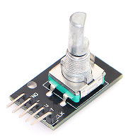
The rotary encoder can be considered as 2 switches which periodically open and close as you turn the encoder shaft. It can be used e.g. to change the volume on a music system or, when connected to a motor shaft, to measure the motor speed or position.
We need 2 square wave signals in order to distinguish the encoder being turned left of right.
 |
| the rotary encoder |
The encoder board has got 5 pins:
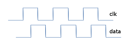
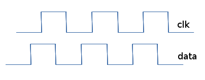
It contains two 10 kΩ resistors to limit the current when the switch is closed. The pulse train on the dt (data) pin with respect to the clk pin is shifted by 90° in such a way that, when turning right, after each transition of the clk signal the data signal is in opposite phase (when clk is high, dt is low and vice versa). When turning left, then the two signals are in phase.
 |
 |
| pulse trains when turning right |
pulse trains when turning left |
Finally the shaft can be pushed down to close a switch, similar to a simple push button. The state of this push button is seen on the sw pin.
--
 Uli Raich - 2017-02-05
Comments
Topic revision: r2 - 2017-02-05
- uli


