The ESP32-CAM module
Introduction
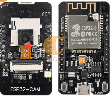
The ESP32-CAM module is dedicated to camera readout. It provides
- an ESP32-S CPU
- a 2 mega pixel OV2640 camera
 and its interface.
- a very bright LED used as a flashlight connected to GPIO 4
- a user LED connected to GPIO 33
- an SD cardholder for SD card with up to 4GBytes capacity
The pinout

The interface for the SD card:
Board Variants
The ESP32-CAM comes in a number of variants.
The original ESP32-CAM
The original version has no USB connector and can only be controlled with a USB to serial adapter.

The connections to the USB to serial adapter are as follows:
In order to flash the board, GPIO 0 (marked IO0) must be jumpered to GND and the board must be reset. This sets the ESP32 to flash mode. Once flashing is finished, the jumper must be removed and the board reset. Thereafter, the board can be accessed with the USB to serial connection and a virtual terminal like minicom or gtkterm.
The ESP32-CAM-MB
The second variant comes with the ESP32-CAM-MB main board, which provides a micro USB connector.

The ESB32-CAM board, to be used with this main board, is slightly modified with respect to the original one:
 |
 |
| The original ESP32-CAM |
The ESP32-CAM modified to work with the main board |
On the modified ESP32 cam board, the pin marked GND/R (just GND, on the original board) is connected to the ESP32 reset pin on the camera board and to the RTS line of the serial port on the ESP32-CAM-MB board. GPIO 0 is connected to serial DTR. Since the Unix serial driver sets RTS and DTR when connecting, the board is always in flash programming mode.
In order to access REPL you must pull both DTR and RTS low. This can be done with gtkterm, which has buttons to toogle these lines, or you can use rshell with DTR and RTS set to "false":
export RSHELL_RTS="false"
export RSHELL_DTR="false"
When trying to run thonny you will hit the same problem. The new version of thonny (I use version 4.0.0-dev) however allows you to disable DTR and RTS in the file
$HOME/config/Thonny/configuration.ini. Just add the 2 lines setting DTR and RTS to False at the end of the file.

The esp32-cam model with the micro USB connector installed
This model works similarly to the original version, but with the micro USB connector and a "flash button" already installed. A simple micro USB cable is needed for communication. In order to set the module to flash mode, hold the flash button while pushing the RST button.

Testing with esp32-who
The github repository
esp32-who provides the esp32-cam driver, as well as a number of example programs. Before trying to integrate the driver into MicroPython I build the camera_web_server example and check that the hardware works correctly:
First configure the application with
idf.py menuconfig
In the Kconfig menu coming up you must
- specify your WiFi setup (SSID and password)
- select the camera type (AI Thinker)
This results in the following GPIO settings:

With these settings, we can build the application and flash it to the board.
idf.py build
idf.py flash
After successful flashing connect minicom (or rshell in the case of the esp32-cam-mb) to the camera module and reset the machine.
Integration into MicroPython
Espressif provides an
esp32-camera
driver, which must be installed in the
components folder of esp-idf. I downloaded it to the same level as esp-idf and micrropython and created a symbolic link to it in esp-idf/components. In order to make sure that the correct esp-idf is used for compilation, I wrote a little shell script setting up the correction environment:

As you can see, it points to the esp-idf to be used, and it makes sure that the correct idf.py, which is stored in esp-idf/tools, is found in the execution path.
--
 Uli Raich - 2021-10-21
Comments


