The Magic Wand Example
Introduction
The magic wand example shows how to detect gestures using an accelerometer. Different types of accelerometers are easily available:
The MPU6050 and the MPU9250 gave hardware offset registers which allow calibrating the device. When the device is horizontally mounted and stationary (not moving) we expect the values:
- 0,0,1g for the measured acceleration in x, y and z, z pointing in the direction of gravity.
- and 0,0,0 for the gyroscope
The measured values may however differ. Setting the hardware offsets for acceleration and gyroscope permit to correct for the offset. The application note;
http://www.digikey.com/en/pdf/i/invensense/mpu-hardware-offset-registers
describes these registers.
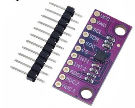
- The LIS2DH MEMS digital output motion sensor from ST Microelectronics is an ultra low power high performance 3 axis accelerometer.

Hardware
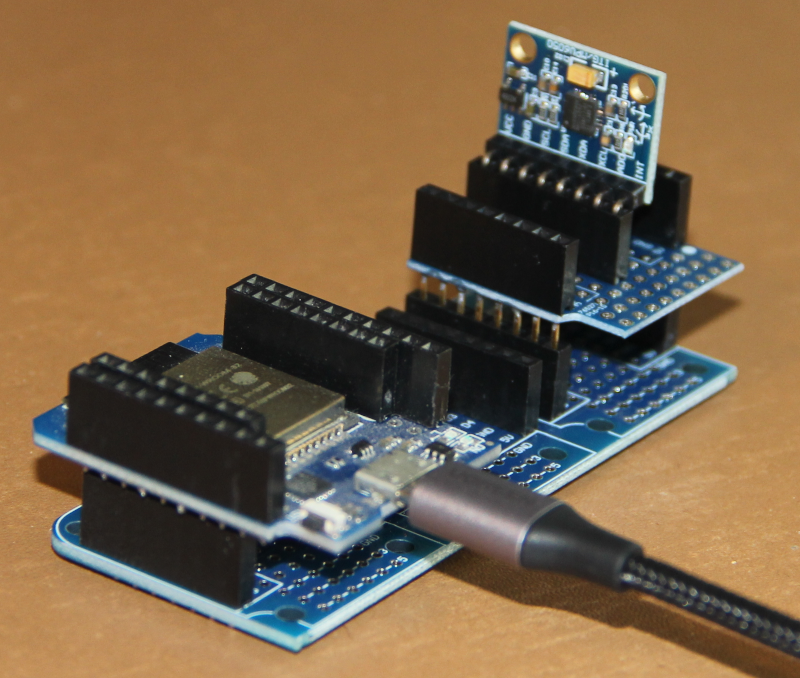
I mounted the accelerometer onto a WeMos D1 prototype board. With the triple base and the CPU this makes up for a stable assembly that can easily be moved without cable contact problems.

Hardware connections
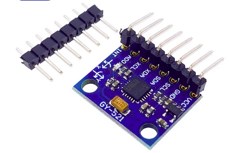
The MPU6050 is connected to the WeMos D1 bus as follows:
XDA and XCL are foreseen to control an external I2C bus, These pins are currently not used. AD0 allows to modify the MPU6050 I2C address and is also not used.
The connections of the MPU92/63 are similar
| MPU92/63 |
!WeMos |
GPIO |
I2C |
SPI |
| Vcc |
5V |
|
|
|
| GND |
GND |
|
|
|
| SCL |
D5 |
GPIO 18 |
SCL |
SCK |
| SDA |
D7 |
GPIO 23 |
SDA |
MOSI |
| AD0 |
D6 |
GPIO 19 |
Alternate module address |
MISO |
| INT |
D1 |
GPIO22 |
|
|
| NCS |
D0 |
|
|
CS |
| FSYNC |
GND |
|
|
|
The ADXL345 is connected as follows:
While the MPU6050 and the ADXL345 use the I2C bus, I connected the LIS3DH to be used with the Serial Peripheral Interface (SPI) or I2C as follows:
| LIS3DH |
SPI pins |
WeMos D1 bus |
GPIO |
| Vcc |
|
3.3V |
|
| GND |
|
GND |
|
| SCL |
SCK |
D5 |
GPIO 18 |
| SDA |
MOSI |
D7 |
GPIO 23 |
| SDO |
MISO |
D6 |
GPIO 19 |
| CS |
CS |
D0 |
GPIO 26 |
| INT1 |
|
D1 |
GPIO 22 |
| INT2 |
|
D2 |
GPIO 21 |
| ADC1 |
|
D3 |
GPIO 16 on ESP32 WROOM, GPIO 25 on ESP32 WROVER-B model T7 V1.5 |
| ADC2 |
|
D4 |
GPIO 17 on ESP32 WROOM, GPIO 27 on ESP32 WROVER-B model T7 V1.5 |
| ADC3 |
|
D8 |
GPIO 5 |
Remark: The LISDH breakout board has 3 SMD jumpers marked "0" on the photo above. These tie ADC channel zero and two to GND and channel one to Vcc. These jumpers must be removed if you want to use the ADC. The ADC however is of limited use as it only works in a range of ~ 800mV to 1.6V.
Providing a training data set
In order to provide a training data set, we must be able to record gestures. We must therefore provide a program that recognizes the start and the end of a gesture (movement and inactivity detection) and which records the accelerometer data of the gesture onto a file. Gesture detection is of course also needed to be able to feed the accelerometer data into the trained model, which will then recognize the gesture.
--
 Uli Raich - 2022-02-02
Comments

 .
.


