TCS3200 Color Sensor
Introduction
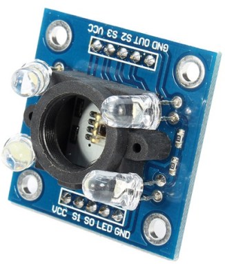
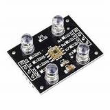
The TCS3200 color sensor comes on PCBs with slightly different layout:
The main difference between these modules is that one of them pulls out the TCS3200 OE (Output Enable) line, while the other one does not.
The TCS3200 uses an array of 64 photo cells, where 16 of the cells are equipped with a red, green or blue filter respectively, while the remaining 16 cells have no filter at all.

The control signals S2 and S3 allow selecting cells with a particular filter:
The color intensity measured is converted into a frequency, which is output on the OUT line, if the output enable is active (which for the module on the left is always the case).

The output frequency is passed through a frequency divider which scales down the frequency output on the OUT line as follows
| S0 |
S1 |
frequency scaling |
| 0 |
0 |
power down, sleep mode |
| 0 |
1 |
2 % |
| 1 |
0 |
20% |
| 1 |
1 |
100% |
This means that with a setting of 2% the frequency is divided by a factor 50.
The LED control line allows switching the illumination LEDs on and off.
Understanding the module and developing a driver for it
The software is available on github:
https://github.com/uraich/TCS3200-MicroPython
First steps
A driver in MicroPython is usually implemented as a Python class. The object creation method __init__ initializes the chip. In case of the TCS3200, the GPIO lines used to control
- the filters (S2 and S3)
- the frequency divider (S0 and S1) if used
- the output enable (if available)
- the LEDs
must be initialized with their respective pins numbers as output signals, and the OUT pin must be initialized as input with internal pull-up.
To have a first preliminary check, we can implement, kin addition to the __init__ method, a method that switches the LEDs on and off. I prefer to also have a debug method allowing me to switch debugging messages on and off.
This is implemented in the
led.py program. Another short MicroPython program:
switchOffLeds.py is provided to switch the LEDs off. This can be run on the ESP32 from the command line using the shell script
switchOffLeds. Make sure that execute permission is given for the script.
To ease development, the driver and the application using it, are combined in the same file. Once the driver is sufficiently tested, these two parts will be separated in two distinct files. The driver will be uploaded to the /lib folder on the ESP32 to make it permanently accessible.
In Python there are no public and private variables. There is however a convention that variables whose names start with the '_' character to be considered private.
Very often, classes have variables that are accessed through getter and setter functions. These can be implemented with the decorators:
- @property
- @prop_setter, where prop is the name of the property to be set
Towards reading the frequency of the OUT signal
In order to better understand the TCS3200 it is necessary to get a feeling for the frequencies it emits. In order to measure this frequency, we must be able to set the filter and the frequency divider. This is done in the program
filter_and_freq.py. The test program sets debugging mode, and it writes and reads back the filter and frequency divider settings.
Measuring the frequency
In order to measure the frequency, the time elapsed for the detection of a number of OUT signal cycles is measured. The number of cycles to be used is set in the
cycles variable. Of course, we again need getter and setter methods to control _cycles. We attach an interrupt handler to the OUT pin (_cbfwhich stands for _callback function). The number of cycles, already measured, is saved in the _cycle (without the "s"). This value is set to zero when the interrupt handler is started (connected to _cbf). When the first rising edge of the signal is seen, the current system clock in us is saved in _start_tick. For each rising edge of the OUT signal, _cycle is incremented until the value In _cycles is reached, in which case the system clock is saved in _end_tick. The duration between the start of the measurement and the moment the number of requested cycles has been seen is then
duration =_end_tick - _start_tick
and the frequency in Hz is 1000000 * _cycles / duration. The factor 1000000 comes from the fact that the duration is measured in us while the frequency is calculated in Hz.
This program is implemented in
meas_freq.py.
It shows that for clear filters, the frequency divider set to 2% and a white target, I measure a frequency of 2.349 kHz. When using a black target, the frequency drops to 380 Hz.

This teaches us an important lesson: The time between two rising edges for the white target is just 435 us. If we change the frequency divider to 20% this time would be reduced to 43 us, which is simply too short an interval for our interrupt handler. The program can handle a 20% frequency divider setting for the black target, in which case the interval is 263 us (1000000/3800), but it will crash for the white target because it will receive new interrupts while the old ones have not been entirely treated.
If we want to read the OUT signal at full speed, then an external high speed counter is needed. Otherwise, we can fix the S0 and S1 signals to 0 and 1 respectively and therefore fix the frequency divider to 2%. This liberates 2 GPIO lines for other purposes.
Timeouts
There is still a problem with the
meas_freq.py program.
The code:
    while tcs3200._end_tick == 0:
        time.sleep_ms(10)
will wait forever, if the number of cycles to be measured, is never reached. This can happen e.g. if the OUT signal is assigned a wrong GPIO pin. The problem can be solved by starting a timeout counter when the measurement is started. This counter can be used to raise an exception if reaching the _cycles limit takes too long.
timeout.py is the same program as
meas_freq.py with the timeout counter added. The timeout is set to 2s. The number of cycles to be measured is set to 10000 in order to provoke the timeout.
Calibration
The formula for the calculation of rgb values is given by:
component = max * (Fv - Fb) / (Fw - Fb) where the variables have the following meaning:
- component: value of the color component measured
- max: maximum value the color component can reach. For many color representations, this is 0xff or 255
- Fv: frequency measured for the color component
- Fb: frequency measured for a black target
- Fw: frequency measured for a white target
This means that we must measure the frequencies of each color component for a black and a white target. This is done in
calibration.py.
Detecting colors
--
 Uli Raich - 2022-05-16
Comments


