Additional Sensors
The sensor kit was originally designed to be used with the Arduino, an Italian micro-controller design very popular with hobbyists. The Arduino uses Atmel micro-controllers with internal flash memories, which can be programmed from a PC through USB. A complete GUI based Software Development Kit (SDK) is available containing editor, cross-compiler and flash programmer. The Arduino is delivered with a boot loader pre-installed which helps in flash programming. Without this boot loader and external flash programmer is needed. The Arduino is much less powerful than the Raspberry Pi but has similar interfaces to the outside world: GPIO, SPI, I2C. In addition to the Raspberry the Arduino has 6 analogue inputs with and analogue to digital converter on chip. This allows to read analogue signals without additional hardware. The sensor kit contains 2 sensors with analogue to digital conversion on the sensor chip (DS18b20 and DHT11) while for other analogue signals an additional external ADC is needed. The additional sensor boards are all based on the I2C bus and include- The PCF8591 8 bit A/D and D/A converter
The ADC has 4 multiplexed input channels and 2 DAC channel and it includes a potentiometer, a photo resistor and a thermistor, which can be connected to the ADC inputs through jumpers. - The ADS1115 16 bit ADC
This is a high resolution ADC again with 4 multiplexed input channels - The MCP4725 Digital to Analogue converter
- The DS1307 Real Time Clock combined with the AT24c32 serial EEPROM
- The BMP180 Temperature and Barometric Pressure sensor
- The HD44780 LCD controller with a 2 x 16 character display and a PCF8574 8bit I/O expander for the I2C bus
- The ISD1820 audio module
- The 3-axis accelerometers
- A stepping motor
 --
-- Comments
| I | Attachment | History | Action | Size | Date | Who | Comment |
|---|---|---|---|---|---|---|---|
| |
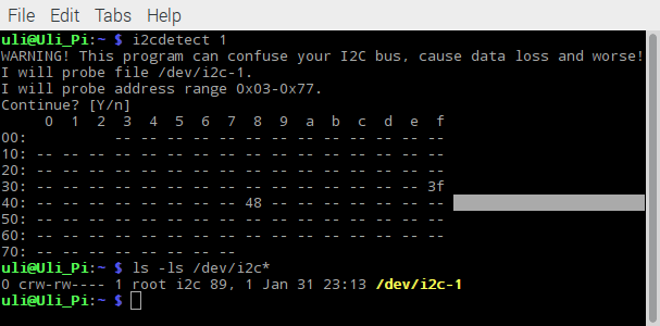
i2cdetect.png | r1 | manage | 29.3 K | 2017-02-01 - 11:59 | UnknownUser |
Ideas, requests, problems regarding TWiki? Send feedback


