Solutions to exercise 9: ADC and DAC
Exercise 1:
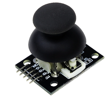
As you can see on the photo, the joystick has 5 pins:| Pin on Joystick | Pin on ESP32 |
|---|---|
| GND | GND |
| 5V | 3.3V |
| URx | GPIO 34 |
| URy | GPIO 33 |
| SW | Switch, can be connected to any GPIO not used for the eercise |
 Creating an instance from the ADC class in the machine module is simple as is reading from it. See http://docs.micropython.org/en/latest/esp32/quickref.html
Exercise 2:
Connect the ESP32 DAC output to the input of the ADC (DAC: GPIO 26, ADC: GPIO 36). Ramp the DAC data, starting from 0 to its max value: 255 in steps of one. Wait for 50ms to be sure the DAC output has settled. Then read the ADC and write the result to a file in ascii format. You can use gnuplot to easily visualize the results.Exercise 3:
For once the driver of the ads1115 ADC is not already included in the MicroPython binary. Before using it, it must be uploaded to the ESP32 flash:ampy mkdir /lib ampy put ads1x15 /lib/ads1x15The first command is only needed if /lib does not exist already on the ESP32. Now we can
from ad1x15 import ADS1115and use it. The program is essentially the same as the one in exercise 2.
Exercise 4:
Explained on the TWiki page ADC and DACExercise 5:
For the exercises an oscilloscope is needed.We have a very cheap Hantek USB oscilloscope in our lab equipment. Connect one of the probes to the output of the DAC ( GPIO 26) and observe the result of your programs on the scope display. ADC and DAC has screen dumps of what you are expected to see. --Comments
Ideas, requests, problems regarding TWiki? Send feedback


